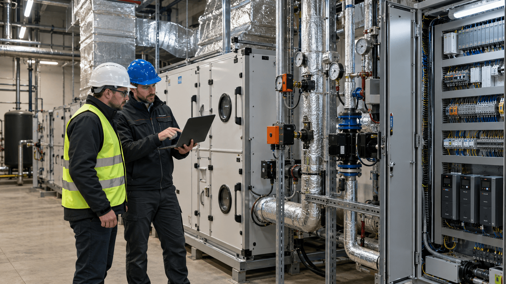
A capacitor bank is primarily used to reduce the inductive reactive power drawn from the grid. In an industrial facility, however, its effectiveness depends on more than the kilovars (kvar) shown on the nameplate. Load variation, step sizes, harmonics and correct control also matter. Before purchasing, establish how much reactive power the equipment should switch in under different operating conditions and whether the network is suitable for a conventional capacitor bank.
When does a capacitor bank make sense?
Capacitors generate capacitive reactive power locally, offsetting some of the inductive reactive power required by connected equipment. This can reduce the inductive reactive power flowing through the supply point. It does not mean that the bank will reduce active energy consumption, measured in kWh, by the same amount. It may, however, reduce current and associated losses in part of the supply system, depending on its location and the load.
Induction motors, transformers and other inductive loads are common reasons to consider a capacitor bank. Where the load varies, an automatic bank is usually needed, with a controller connecting the appropriate number of steps. A fixed bank may be suitable where reactive power demand is almost constant, but its operation at minimum load must be assessed.
A capacitor bank is not a universal remedy for every reactive energy charge in Poland. If the problem is capacitive reactive power being exported to the grid, adding capacitors can make matters worse. The first step is therefore to distinguish the type of reactive power flow, and only then select the equipment. We explain these types in more detail in our article on reactive power compensation.
How to size a capacitor bank
Capacitor bank sizing should be based on variations in active power P and reactive power Q, not solely on transformer rating, a single invoice or the total motor rating. In Poland, electricity bills show the scale and type of reactive energy being charged for, but not when a particular number of kvar is required. An electricity distribution bill analysis, supplemented by electrical measurements, provides useful input.
What information is needed before sizing?
- P and Q profiles over time: at least representative days and production shifts, including start-ups, shutdowns, weekends and low-load operation. A 15-minute profile can reveal overall trends, but may miss rapid changes that require more frequent sampling.
- Sign convention and calculation of Q: distinguish inductive reactive power import from capacitive export. With distorted waveforms, check the quantity definitions used by the power analyser and the controller.
- Network characteristics: voltage, short-circuit power or transformer data, switchboard diagrams, the proposed connection point and existing protection devices.
- Voltage and current harmonics: at least the levels and significant harmonic orders under different operating conditions. The installed capacity of drives or rectifiers alone is no substitute for a resonance risk assessment.
- Operating conditions: temperature, ventilation, dust, switchboard space, maintenance access, the existing controller and current-transformer connections.
A well-planned measurement campaign should cover the operating conditions relevant to sizing. IEC 61000-4-30:2025 describes power quality measurement methods, including harmonics. It does not specify a universal capacitor bank rating suitable for every industrial site.
Preliminary calculation versus actual sizing
For a simplified case involving sinusoidal waveforms and a steady load, the compensation requirement can be estimated using Qc = P × (tg φ₁ − tg φ₂), where P is active power and φ₁ and φ₂ represent conditions before and after the intended compensation. This is a preliminary estimate, not a complete capacitor bank design. The calculation is also presented in Schneider Electric’s Electrical Installation Guide.
Worked example. Consider two hypothetical operating conditions at a plant. For comparison, assume that inductive reactive power after compensation should not exceed 0.30 times active power. At a real facility, the target must be determined from installation characteristics and the applicable billing rules.
| Parameter | Production | Low load |
|---|---|---|
| Active power P | 200 kW | 60 kW |
| Inductive reactive power Q before compensation | 120 kvar | 30 kvar |
| Indicative target Q = 0.30 × P | 60 kvar | 18 kvar |
| Resulting difference Qc | 60 kvar | 12 kvar |
At full production, this model would call for approximately 60 kvar of compensation, but only 12 kvar at lower load. Keeping 60 kvar permanently connected under the second condition would result in Q = 30 − 60 = −30 kvar, i.e. an excess of capacitive reactive power. This simple example shows why the bank’s total rating must not be confused with the power that should remain connected continuously.
Capacitor bank steps and controller settings
An automatic bank divides its total rating into switchable sections known as steps. The controller assesses demand and connects or disconnects steps to maintain the specified target without excessive switching or overcompensation. The important factors are therefore not only the total kvar rating but also the smallest step size and the available combinations.
In our illustrative example, a configuration of four steps with usable ratings at operating voltage of 10 + 10 + 20 + 20 kvar could be considered. All 60 kvar would be available during production, while at low load one 10 kvar step would leave Q = 20 kvar rather than 18 kvar. The actual step configuration, switching logic and settings must nevertheless be assessed against the full profile, not just two example operating points.
The following factors have a particularly strong influence on performance:
- Current transformer position and polarity: the controller must measure the correct current for the entire part of the installation it is intended to compensate. An incorrect measurement can cause improper control responses.
- CT ratio, voltage sensing and target setting: these must match the actual supply configuration and the controller manufacturer’s instructions.
- Switching delay and capacitor discharge time: a step must not be reconnected before the manufacturer-specified interval has elapsed. Excessive switching stresses the equipment.
- Suitable switching devices: capacitor-duty contactors and inrush-current limiting devices must be selected for the operating conditions, not as though the bank were an ordinary resistive load.
- Step monitoring: alarms, operation counts and actual power available from each step should be verifiable during maintenance.
If demand changes faster than a contactor-based system can safely follow, simply choosing smaller steps may not be enough. Other switching or compensation technologies should then be assessed.
Capacitor banks with detuning reactors: when are they needed?
Capacitors interact with the inductance of transformers and cables, potentially creating resonance and amplifying certain harmonics. This is especially relevant in installations with non-linear loads such as variable-frequency drives, rectifiers and power-electronic supplies. It is not enough to observe that a plant has drives; harmonics and supply characteristics must be assessed.
In a detuned capacitor bank, a detuning reactor is connected in series with each relevant capacitor step. Together they form a circuit with a selected series-resonant frequency. Its main purpose is to limit adverse harmonic effects and the risk of capacitor overload. Such an arrangement should not be confused with a filter designed to remove a specified level of harmonics. Selection principles are discussed by Schneider Electric and in ELHAND’s technical guide to reactors.
A common detuning factor is p = 7%. On a 50 Hz system, this corresponds to an approximate series-resonant frequency of 189 Hz (50/√0.07), below the fifth harmonic at 250 Hz. It is not a universal setting: significant lower-order components, other network configurations or special loads may require a separate analysis. Capacitor rated voltage, the rating of the complete reactor-equipped step and thermal losses also matter.
A detuning reactor is not the same as a reactive power compensation reactor
| Component | Connection and purpose | What must not be assumed |
|---|---|---|
| Detuning reactor | Connected in series with the capacitor in a bank step; changes the system’s response to harmonics. | It is not a standalone means of reducing capacitive reactive power exported by the entire site. |
| Reactive power compensation reactor | Consumes inductive reactive power, usually in a shunt connection to the network, to reduce excess capacitive reactive power. | It does not automatically provide protective detuning for existing capacitor steps. |
Both types may appear in a design for different reasons. The word “reactor” in a quotation is not enough to establish its function.
Harmonics, overcompensation and changing loads
In manufacturing plants, problems may arise from changing conditions rather than an error in the bank’s nameplate rating. After shutting down a line, revising schedules, adding drive systems or commissioning photovoltaic generation, the relationship between P and Q may differ from that at the time of original sizing.
Three phenomena deserve particular attention:
- Overcompensation: as demand falls, the controller leaves an oversized step connected or the bank has a fixed rating. Capacitive reactive power then appears at the metering point.
- Harmonics and resonance: higher harmonic currents may overload capacitors, reactors and protection devices. THD alone, whether low or high, is insufficient to design the entire system. Harmonic orders and network impedance are also needed.
- Rapid fluctuations: frequent changes in Q can cause contactors to switch continuously or leave the system outside the target range between operations.
In networks with distorted waveforms, true power factor must not be confused with cos φ for the fundamental component. A capacitor bank mainly compensates phase-displacement reactive power; it does not automatically eliminate current distortion. The distinction is explained in the Electrical Installation Guide.
What should the design, quotation and commissioning report include?
Purchasing a cabinet based solely on a “60 kvar” claim does not guarantee correct operation once installed. Quotations should be compared using the same set of input data and expected outcomes.
| Document or stage | What to check |
|---|---|
| Assumptions and measurements | Measurement points, periods and operating modes, P/Q profiles, harmonics, required performance at the billing point and conditions after modernisation. |
| Sizing documentation | Usable power at operating voltage, number and ratings of steps, reactor type, selection criteria, control method, spare capacity and conditions under which compensation is restricted. |
| Design and diagrams | Connection point, CT position, protection and cable sizing, short-circuit conditions, selectivity, ventilation, heat dissipation and maintenance access. |
| Quotation | Exact configuration of capacitors, reactors, controller, switching devices, protection, measurements, commissioning and required documentation. |
| Commissioning report | Controller settings, correct P/Q readings and directions, current and operation of successive steps, response at low and high load, alarms, measurement results and parameters to monitor. |
When evaluating equipment, consider the scope of IEC 61921:2017 for low-voltage power factor correction banks and IEC 60831-1:2014 for low-voltage self-healing capacitors. These standards specify requirements for defined products and their tests; they do not replace installation-specific engineering design. Also verify the editions of standards cited in the design and the manufacturer’s requirements.
Technical commissioning should demonstrate the bank’s behaviour under actual operating conditions, not merely the presence of voltage and the absence of alarms. If prolonged testing across different production conditions is not possible, arrange a follow-up check of settings and performance once normal operation resumes.
Operation: what most often deteriorates?
A bank can still appear serviceable and show normal controller operation even when some steps no longer deliver their expected power. Possible causes include a loss of capacitance, a failed contactor, a tripped protection device, excessive temperature or incorrect configuration after switchboard work.
A maintenance plan should include:
- comparison of controller settings with the current load profile and a review of alarm history;
- measurement of current and actual operation at every step, with checks of fuses and contactors;
- condition and temperature of capacitors, connections and reactors, together with ventilation performance;
- signs of overheating, deformation, contamination, moisture and an excessive number of switching operations;
- comparison of measured results with the commissioning report and any changes to connected equipment.
Inspection intervals should be based on operating conditions and the instructions for the specific equipment. For example, Schneider Electric’s maintenance guide for PowerLogic PFC and EasyLogic PFC banks describes inspection tasks and periodic maintenance. Only authorised personnel may work inside the bank, after isolating the supply and verifying the absence of voltage, including residual voltage on the capacitors. Safe discharge time must be determined from the equipment documentation, not from a universal assumption for all banks.
Common sizing and modernisation mistakes
| Mistake | Why it is a problem | How to avoid it |
|---|---|---|
| Sizing the entire bank from one invoice | No information on minimum load or how rapidly Q changes. | Measure a representative P/Q profile and review billing data. |
| Smallest step is too large | The controller cannot adjust power accurately at low load. | Check control resolution and available step combinations. |
| Selecting a bank without a harmonic assessment | Risk of resonance, increased currents and accelerated component wear. | Assess harmonics and network parameters before choosing a plain or detuned configuration. |
| Incorrect current transformer or settings | The controller detects the wrong power flow and operates in the wrong direction. | Verify diagrams, CT ratio, polarity and commissioning tests. |
| Overlooking ventilation and maintenance | Higher temperatures and an uncontrolled decline in reliability. | Specify thermal requirements, maintenance access and inspection intervals. |
| No reassessment after a plant upgrade | A previously well-sized system no longer matches the new load profile. | Reassess after significant changes in loads, drives, PV or operating schedules. |
How to decide on buying or upgrading a capacitor bank
A sensible sequence is to identify the billing issue, collect the load profile, examine harmonics, compare technical options and only then select the total rating and step sizes. At sites dominated by inductive reactive power and relatively slow load changes, an automatic bank may be suitable. Significant capacitive reactive power export, heavily distorted waveforms or rapid changes may call for a different configuration or technology. The choice should be based on measurement and analysis, not the equipment label.
If you are planning a new bank or experiencing problems with an existing one, describe how your installation operates and send Energy Trend the information you have: invoices, available P/Q profiles, harmonic measurement results, controller details and information on temperature and enclosure conditions. You do not need every document at the initial stage. Based on the description and available data, we can identify what else is needed for reliable sizing. Contact: audytor@energytrend.pl.
Technical and standards references
- Schneider Electric, Electrical Installation Guide — principles of calculating compensation power.
- Schneider Electric, Electrical Installation Guide — harmonics and detuning reactors.
- ELHAND, Technical Guide — protective reactors for capacitor banks.
- IEC 61921:2017 — low-voltage power factor correction banks.
- IEC 60831-1:2014 — requirements for low-voltage self-healing capacitors.
- IEC 61000-4-30:2025 — power quality measurement methods.
- Schneider Electric, PowerLogic PFC and EasyLogic PFC — maintenance guide.