Additional reactive energy charges can appear on an electricity bill after a change in plant operating conditions, a lighting upgrade, the commissioning of new drives, photovoltaics or other power-electronic equipment. The first reaction is often simple: “we need to install a capacitor bank”. In practice, this shortcut can lead to an incorrectly selected compensation system.
Reactive power compensation makes sense when we know not only the amount of the charges, but above all their cause, the type of reactive power and how it changes over time. In some cases, an automatic capacitor bank will be the right solution. At another site, compensation reactors, a detuned capacitor bank or an active solution may be required. Sometimes there is no need to buy another device at all – the existing system should first be reconfigured or repaired.
What is reactive power and why does it matter for an electrical installation?
In simplified terms, in an AC installation we analyse, among other things:
- active power P [kW] – the power converted into useful work, heat, light or motion,
- reactive power Q [kvar] – associated with the periodic exchange of energy required, among other things, to produce electric and magnetic fields,
- apparent power S [kVA] – a quantity describing the loading of the source and current paths; with distorted waveforms, the relationships between P, Q and S are more complex than for an ideal sine wave.
Reactive energy does not perform useful work in the same sense as active energy, but its flow affects currents in the installation and the loading of cables, transformers and other network components. For this reason, the way reactive energy is drawn from or fed into the grid may be subject to settlement by the operator.
The most important practical distinction concerns the nature of reactive power:
- inductive – typical primarily of equipment using magnetic fields, such as motors and transformers,
- capacitive – associated, among other things, with cable capacitance, capacitors and the operating characteristics of some power-electronic equipment.
Caution is needed with the term “negative reactive power” used by some meters and monitoring systems. A minus sign may indicate capacitive behaviour, but this is not a universal rule for every device. Different meters may use different sign and quadrant conventions, so the documentation for the specific metering system must be checked before the data are interpreted.
Likewise, cosφ should not automatically be equated with the total power factor PF. With nonlinear loads and harmonics, cosφ describes the phase shift of the fundamental component, whereas actual PF also includes distortion. This matters when assessing installations with variable-frequency drives, rectifiers or electronic power supplies.
Where do reactive energy charges come from?
In Poland, the settlement rules are currently set out in § 47 of the tariff regulation. For inductive reactive energy, the key parameter is tgφ, which for settlement purposes is calculated as the ratio of reactive energy to active energy drawn in the same period or time zone. The current wording of the provision can be checked in ELI.
The contractual tgφ0 value should be stated in the connection conditions, the distribution agreement or the comprehensive supply agreement. If it is not specified, tgφ0 = 0,4 is used for settlement. The Polish regulation permits a lower value where justified by an individual expert assessment, but tgφ0 may not be lower than 0,2.
Under the Polish regulation, customers supplied from medium-, high- and extra-high-voltage networks are expressly subject to settlement for excess reactive energy. Customers connected to networks with a rated voltage not exceeding 1 kV may also be covered by such settlement.
In practice, three situations must be distinguished:
- excess inductive reactive energy consumption, when tgφ exceeds the contractual tgφ0,
- inductive reactive energy consumption when no active energy is being consumed,
- capacitive reactive power – overcompensation, both when active energy is being consumed and when it is not.
For capacitive reactive energy, there is no analogous “free allowance” of tgφ0 = 0,4. The Polish regulation bases settlement on the surplus reactive energy fed in above the level corresponding to tgφ = 0.
The invoice therefore does not show a “penalty” in the colloquial sense, but a tariff charge calculated according to the Polish regulation and the tariff of the relevant DSO. The actual amount depends, among other things, on the registered energy quantities, the metering method, the tgφ and tgφ0 values and the parameters of the operator’s applicable tariff.
What should be checked on invoices before selecting equipment?
From an auditor’s perspective, the first step is not to select a capacitor bank, but to build a picture of the problem from billing data.
It is best to collect at least one full representative period – usually 12 months; where seasonality or technological changes are significant, a longer period is useful. The analysis should be performed separately for each PPE (Polish electricity metering point).
The following should be checked on the invoices:
- whether there is a charge for inductive reactive energy, capacitive reactive energy, or both,
- the amount of reactive energy billed in kvarh or Mvarh,
- the charge amount in each month,
- active energy consumption in the corresponding period and time zone,
- whether settlement is performed around the clock or in specified time zones,
- whether the problem occurs continuously, seasonally or only in selected months,
- whether the charges appeared after a specific technological change,
- which tgφ0 value is stated in the agreement or connection conditions,
- whether the data relate to one or several PPEs.
It is particularly important to separate inductive and capacitive charges. If a company has undercompensation in some periods and overcompensation in others, a simple fixed-power system may be the wrong solution.
A simple example – what an invoice tells you and what it does not
Assume that the following were registered in the same billing time zone and period:
- active energy: 100 MWh,
- inductive reactive energy: 50 Mvarh.
Then:
tgφ = 50 / 100 = 0,50.
If tgφ0 = 0,40 applies under the agreement, the billing threshold has been exceeded. This is sufficient reason to investigate the problem, but it is not a basis for ordering a capacitor bank of a specific kvar rating. The charge for exceeding tgφ0 itself is determined by a separate tariff formula in the Polish regulation.
A monthly invoice does not show whether the 50 Mvarh was generated evenly throughout the month or mainly while several large loads were operating, nor how quickly Q changed. It also does not show harmonic levels.
When are invoices alone not enough?
Invoices are very useful for assessing the scale of the cost. For selecting compensation equipment, they are usually insufficient.
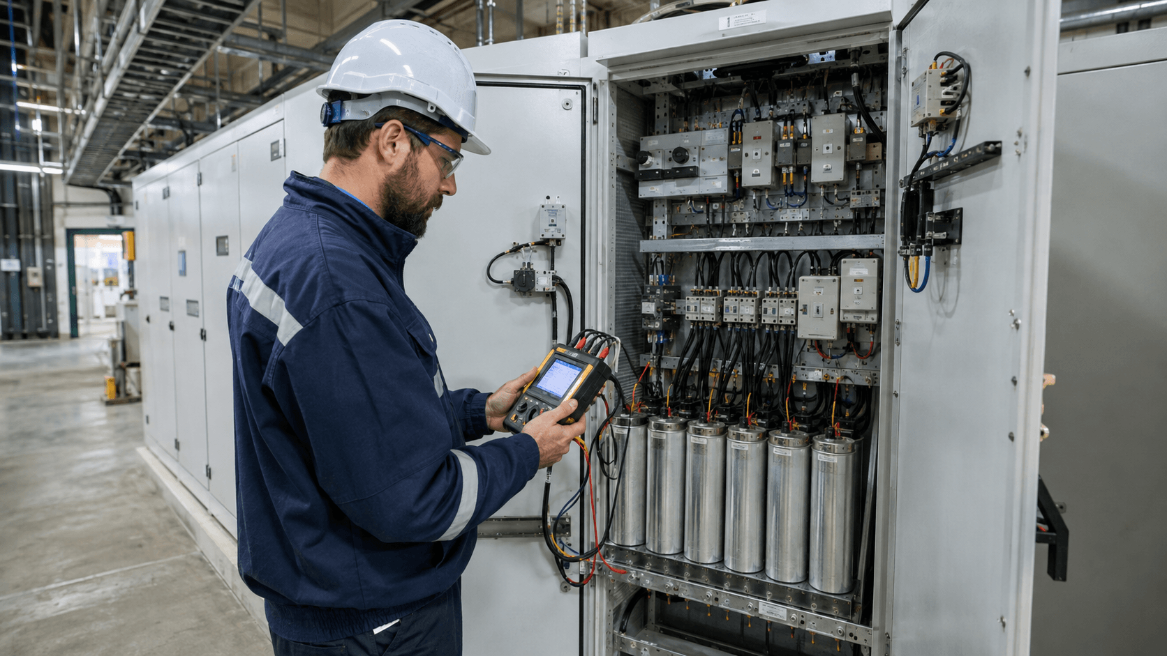
Before selecting a solution, it is necessary to know when, where and under which operating state of the installation reactive power occurs. Depending on the site, this means analysing data from meters, an EMS/BMS, or taking measurements with a power quality analyser.
Measurements should cover representative operating states of the plant: production, shutdowns, night operation, weekends, start-ups, low-load operation and – where relevant – operation of local energy sources. There is no single universal number of measurement hours suitable for every company. The measurement period should cover the complete cycle relevant to the problem in question.
15-minute or hourly profiles can show the repeatability of a billing issue well, but with rapidly changing loads they may be too aggregated to select the dynamics of the compensation system. The logging resolution must be matched to actual load changes.
In practice, we analyse primarily:
- P, Q and S over time,
- the direction and nature of reactive power,
- PF and cosφ – with these quantities distinguished in the presence of harmonics,
- phase voltages and currents,
- load unbalance,
- voltage and current THD,
- the harmonic spectrum, where it may be relevant to system selection,
- the installation’s response to switching large loads on and off,
- operation of existing capacitor-bank or reactor stages,
- the relationship between Q and the state of the process.
In larger installations, measurement only at the point of connection may not be enough. It is often necessary to go deeper – to switchboards, transformers or groups of loads – in order to identify the source.
Why do load type and load variability determine the solution?
Two plants may have a similar monthly reactive energy charge and still require completely different actions.
Motors and transformers
Induction motors and transformers are typical inductive loads. The problem may be particularly visible at low load, when the share of reactive power relative to active power increases.
If the load is stable, individual or group compensation may be technically justified. If the number of operating machines changes substantially, stepped control or a dynamic solution is more often required.
Variable-frequency drives, power supplies, UPS systems and other power-electronic equipment
It should not be assumed in advance that all electronic equipment will have the same reactive-power characteristics. This depends on the device design, PFC circuit, load and control settings.
The same applies to variable-frequency drives and other converters. In some devices, parameters related to power factor or Q control can be changed in software. Therefore, before installing an additional compensator, it is worth checking the settings and capabilities of the device itself.
LED lighting
The statement “we now have LEDs after the upgrade” is not enough to conclude that capacitive reactive energy is the cause. LED drivers can behave differently depending on the input stage, load and PFC solution used.
If the charges appeared after a lighting upgrade, the Q profile should be compared before and after the change or, at a minimum, the installation should be measured while the lighting is operating and while it is off.
Cables, low-load periods and local sources
Long cables have capacitance and, at low load, may have a noticeable effect on the capacitive reactive power balance. A similar issue may be visible at night, when most loads are switched off but part of the infrastructure remains energised.
After changes such as installing photovoltaics, an energy storage system or new converters, power-factor and Q-control settings should also be checked. The problem may be caused by device configuration rather than by the absence of another compensator.
When does a capacitor bank make sense?
A capacitor bank is a typical solution when the problem is excessive inductive reactive power. Capacitors supply reactive power of the opposite nature locally, reducing its flow through the billing point.
This does not mean that every installation should receive a single fixed capacitor bank. Depending on the load profile, the solutions used include:
- individual compensation for a specific, stable load,
- group compensation for a selected part of the installation,
- a central automatic stepped capacitor bank,
- faster switching systems or active solutions for more dynamic loads.
With a variable load, the key factors are how the bank rating is divided into stages, the minimum stage rating and the controller logic. An oversized first stage or incorrect settings can cause the system to alternate between undercompensation and overcompensation.
A compensation reactor and a detuning reactor are not the same thing
This distinction is easy to misunderstand.
Compensation reactors – for example, adjustable or stepped reactor banks – can be used to compensate excessive capacitive reactive power. They absorb inductive reactive power and balance the capacitive nature of the installation.
By contrast, reactors connected in series with capacitors in a detuned bank serve a different purpose. They shift the resonance conditions of the system and reduce the risk of adverse harmonic effects on the bank and the installation. Manufacturers of such solutions indicate their use with variable loads and in the presence of harmonics. One example is the Schneider Electric VarSet Detuned documentation.
Therefore, before ordering a “bank with reactors”, it must be established whether the objective is to compensate capacitive Q or to detune a capacitor bank.
When is a detuned capacitor bank needed?
If the installation contains many nonlinear loads – for example variable-frequency drives, rectifiers or other power-electronic equipment – harmonic levels and network parameters should be checked.
Capacitors affect the impedance of the installation. An incorrectly selected conventional bank in a network with significant harmonic content may increase the risk of resonance, higher harmonic currents and component overload.
In such a situation, capacitor banks with detuning reactors are among the options considered. The decision should be based on measurements and network analysis, not merely on the fact that variable-frequency drives are present at the plant.
When should active compensation be considered?
Static var generators (SVGs) can rapidly supply or absorb Q and compensate both inductive and capacitive reactive power. This type of solution may make sense where the load changes rapidly, the installation alternates between inductive and capacitive behaviour, or continuously variable control is required. An example of this type of device functionality is described in the CIRCUTOR SVG documentation.
This does not mean that an active solution is automatically better than a capacitor bank. With a slowly varying, typically inductive load, a conventional automatic capacitor bank may be simpler and more economical.
It is also important to separate two functions: reactive power compensation and harmonic filtering. An SVG is primarily used for dynamic Q correction. An active harmonic filter has a different primary function. Some devices can combine these tasks, but this should be confirmed in the documentation for the specific model rather than inferred from the term “active compensation”.
What can happen if compensation is incorrectly selected?
An incorrectly selected system may not only fail to eliminate the charges. It can also create a new problem.
The most common risks include:
- overcompensation – excessive capacitor rating causes the installation to become capacitive and may generate new charges,
- undercompensation – insufficient rating or an incorrect division into stages leaves part of the inductive charges in place,
- resonance and increased harmonic effects,
- overloading and overheating of capacitors or reactors,
- excessively frequent stage switching, shortening the service life of switching components and capacitors,
- incorrect controller response due to an incorrectly positioned or oriented current transformer,
- compensating the wrong part of the installation in relation to the billing point,
- failure to adapt to technological changes – for example after replacing drives, adding PV or changing the operating schedule.
It is particularly risky to size a bank on the basis of a single value from an invoice or by reasoning that “it used to be 100 kvar, so let’s install something similar”.
When is the problem caused by operation or configuration rather than by the absence of equipment?
This is one of the most important stages of diagnosis.
Before investing, it is worth checking whether:
- the existing capacitor bank is not operating at night when inductive loads are switched off,
- the controller has the correct setpoint and interprets the direction of Q correctly,
- the current transformer is installed in the correct location and orientation,
- all bank stages actually switch in,
- the capacitors have not lost capacitance and the switching and protection equipment is serviceable,
- after changes to the installation, old compensation sized for the previous profile has not been left in place,
- variable-frequency drives, UPS systems, the PV installation or other converters have the correct power-factor and Q settings,
- during non-production periods, components causing unnecessary Q flow are not left energised,
- the locations of metering and compensation correspond to the actual reactive power flow.
The Polish regulation also provides for a situation in which the configuration of the network and metering system does not correctly represent the actual reactive-energy flows. This is another reason not to select equipment solely from an invoice when results are unusual.
In practice, what may be needed is repair of failed stages, correction of controller settings or a change in the operating logic of the existing bank rather than the purchase of a new device. The opposite can also occur: the system operates correctly, but the plant profile has changed so much that the existing compensation no longer suits the installation.
What does a sensible diagnostic and compensation-selection process look like?
In practice, it is worth going through six stages.
1. Invoice and contract analysis
First, determine the type of charge, its scale, tgφ0, billing zones, PPEs and when the problem first appeared.
2. Verification of measurement data
If profiles from the meter or monitoring system are available, check P and Q over time. If data are missing or too aggregated, plan measurements.
3. Identification of sources
Correlate the reactive-power profile with the operation of equipment: motors, transformers, lighting, drives, UPS systems, PV installations, cables and existing compensation.
4. Assessment of dynamics and power quality
Check how quickly the load changes and whether harmonics, unbalance or other parameters affect the choice of technology.
5. Technical option
Only at this stage should a choice be made between fixed compensation, an automatic capacitor bank, a detuned bank, reactors, an active system or correction of the existing installation.
6. Post-implementation verification
After commissioning the system, the result must be verified in measurements and subsequent bills. The fact that the controller displays cosφ close to 1 is not sufficient – especially in an installation with nonlinear loads. The difference between PF and cosφ in the presence of harmonics is illustrated well in the Schneider Electric documentation.
When does compensation make economic sense?
There is no universal charge threshold above which compensation should always be installed. The economic decision should be based on data for the specific installation.
Before investing, at least the following should be compared:
- the recurrence and annual scale of charges that can genuinely be reduced,
- installation operating modes – production, shutdowns, seasonality and future changes,
- the cost of equipment, engineering, installation and commissioning,
- the cost of periodic servicing and replacement of wear components,
- the risk that part of the charges will remain with a variable profile,
- the alternative of repairing, retuning or rebuilding the existing compensation system.
The most important point is not to assume automatically that 100% of historical charges will disappear after the equipment is installed. First, estimate what portion of the cost is caused by the issue that the selected solution actually addresses.
Can reactive energy charges be eliminated completely?
In many installations they can be reduced very substantially, and under stable conditions they may also be brought down to zero in subsequent billing periods, but this should not be guaranteed without analysis.
The installation profile changes with the season, the commissioning of new loads, low-load operation and changes in local energy sources. With capacitive reactive power, even periodic overcompensation may reappear in billing.
The objective of correctly selected compensation is therefore not to “install as many kvar as possible”, but to maintain the appropriate reactive power balance under the site’s actual operating conditions.
What should be prepared for a reactive power compensation analysis?
Before the analysis, it is worth collecting:
- electricity and distribution invoices for the last 12 months,
- the distribution or comprehensive supply agreement and the connection conditions,
- information on tgφ0,
- 15-minute or hourly profiles, if available,
- a single-line diagram of the installation,
- information on transformers and large loads,
- data for the existing capacitor bank, reactors and controller,
- information on PV, UPS systems, variable-frequency drives and major upgrades,
- the plant operating schedule.
This set of information is usually enough to assess whether an on-site measurement is required and where it should be taken.
The key principle: identify the cause first, then choose the equipment
Correctly selected reactive power compensation can reduce charges and reactive current flow in the installation. Incorrectly selected compensation can shift the problem from undercompensation to overcompensation, increase the risk of adverse resonance phenomena, or simply fail to keep up with the actual load profile.
The sequence should therefore always be the same: invoices and contract → measurement data → source identification → assessment of dynamics and harmonics → technology selection → verification measurement after commissioning.
If you want to verify whether the charge results from compensation sizing, configuration of the existing system or the load profile, contact Energy Trend and prepare your invoices and – if available – measurement profiles.
Sources
- ELI – consolidated text of the tariff regulation, including § 47
- RCL – status and transitional provision concerning the tariff regulation
- URE (Polish Energy Regulatory Office) – list of electricity tariff regulations
- Schneider Electric – VarSet Detuned Capacitor Banks
- Schneider Electric – Power Factor PF and cosφ Measurement
- CIRCUTOR – Static Var Generator