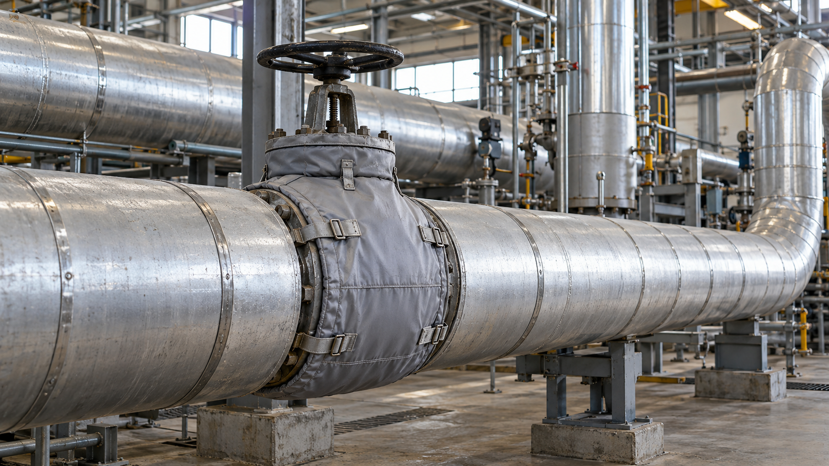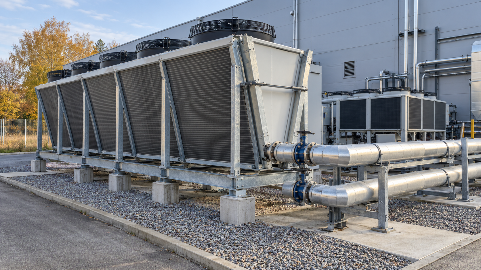
A plant’s compressed air distribution system should deliver the right flow, pressure and air quality to each point of use, including during the highest actual demand. Its performance depends not only on the compressors but also on the arrangement of the distribution mains, pipe diameters, valves and fittings, air treatment and acceptance procedures. Below we explain which data to gather for the design, how to compare options and what to verify before putting the network into service.
Where should you start when designing a compressed air piping system?
Start by establishing the requirements of the machines and processes. Neither the combined compressor capacity nor the diameter of an existing connection is enough to design a new main. When expanding a plant, you need to know where the points of use will be located, which machines run simultaneously and how often short periods of high demand occur.
| Design input | Why is it needed? |
|---|---|
| Equipment list and point-of-use locations | Determines main routes, branch lengths and the need for isolation valves. |
| Nominal flow, peak flow and operating cycle | Establishes section loads when machines operate simultaneously, rather than just average consumption. |
| Minimum pressure required at the equipment | Defines the allowable total pressure loss from the source to the point of use. |
| Air purity class and pressure dew point | Affects air treatment, material selection and any additional filtration at individual points of use. |
| Plant layouts, obstructions and environmental conditions | Allows assessment of pipe routes, supports, clashes, temperatures and maintenance access. |
| Expansion plans and permissible production shutdowns | Helps plan spare flow capacity, network isolation and phased installation. |
Flow documentation must state the reference conditions. Values in m³/h, Nm³/h and compressor capacities quoted at specified conditions are not automatically comparable. Likewise, gauge pressure bar(g) must be distinguished from absolute pressure bar(a).
If the new network is to be connected to a system already in operation, flow and pressure measurements across representative production shifts can reveal constraints that the documentation does not show. The full scope of such an assessment is covered separately in our compressed air system audit; here we focus on distribution design decisions.
Ring main or branched distribution network?
A ring main can supply some points of use from two directions. In a larger hall with fluctuating demand and several production zones, it may reduce pressure losses and make phased upgrades easier. The benefit depends, however, on loop length, pipe diameters, where the equipment is located and whether the relevant valves are open. Simply closing a pipework loop does not guarantee proper operation.
A linear or branched arrangement is simpler and may be sensible where there are few points of use, a short route or a separate production line. Its weakness may be the most distant endpoint, which receives air through all the upstream pipe sections and local restrictions.
Before choosing, compare both options at the same peak flows. Calculations should use actual pipe routes, not straight-line distances. Where the process allows, it is also good practice to be able to isolate part of the network for repairs without shutting down the entire plant.
How should you select pipe sizes for a compressed air system?
The internal diameter is selected for the flow through each section and the allowable pressure drop. Pipe length, the number of elbows, tees, valves and quick couplings, material roughness, operating pressure and temperature all matter. The nominal diameters of different piping systems do not necessarily correspond to the same internal diameter.
- Determine the design flow through each main and branch for justified simultaneous-use scenarios.
- Establish the minimum inlet pressure required by the most demanding item of equipment.
- Allocate the available pressure-drop budget among air treatment, the main, branches and local fittings.
- Calculate frictional and local losses along the critical routes, using actual flow parameters and manufacturers’ data.
- Compare pipe diameter options for planned expansion as well as peak demand.
This approach to sizing is discussed, for example, by an equipment manufacturer in Atlas Copco’s guidance on sizing compressed air piping. It is a manufacturer’s technical resource, not a universal table that can replace engineering calculations.
Example: allocating the pressure-drop budget to a machine
As an illustrative example, assume that the pressure downstream of the air treatment system is 7.10 bar(g) at the design flow and that the equipment needs at least 6.50 bar(g). The calculated losses for the option considered are 0.25 bar in the main, 0.10 bar in the branch and 0.18 bar in the fittings at the machine.
Pressure available at the point of use = 7.10 − 0.25 − 0.10 − 0.18 = 6.57 bar(g). The margin above the required 6.50 bar is only 0.07 bar. Higher momentary demand or a clogged filter could consume that margin. This illustrates the pressure-balance method; it is neither an actual plant measurement nor a recommendation for universally acceptable losses.
Do not automatically make up for insufficient pressure by raising the compressor setpoint. First identify the restriction: a pipe, filter, regulator, hose or quick coupling. The U.S. Department of Energy’s guide to compressed air systems recommends assessing the entire path from generation to points of use and measuring pressure at several locations.
Condensate, dew point and required air quality
Atmospheric air contains water vapour. Some of that moisture can condense after compression and cooling, so network design must address drying, separation and condensate drainage. Where condensation may occur, allow for suitable slopes in the mains, drain points and take-offs that limit water carryover to equipment. Do not assume every installation is completely dry at all times.
Air-quality requirements should be defined for the process or equipment. ISO 8573-1:2010 classifies compressed air purity by particles, water and oil. It does not prescribe one class for every plant. Equipment sensitive to moisture or contamination may need additional treatment at its point of use, rather than specifying higher purity throughout the network than other equipment needs.
The design and acceptance documentation should specify the pressure dew point, including the measurement pressure, where air quality is to be checked and how condensate is to be handled. Drains, separators and filters must remain accessible for maintenance. A leaking or permanently open drain can itself waste compressed air.
Which piping materials are suitable for an industrial plant?
Choose the material according to pressure, temperature, environment, cleanliness requirements and installation method. What matters is the suitability of the entire piping system—pipes, fittings, seals, supports and valves—not just a declaration about the pipe itself.
| Option | When should it be considered? | What should be checked? |
|---|---|---|
| Aluminium compressed air piping system | Expansion projects and frequent workstation rearrangements; modular installation. | Permitted operating conditions for the system, fittings, supports and modification options. |
| Galvanised steel or other steel piping systems | Mechanical requirements or an existing compatible installation. | Risk of internal corrosion, joining method, weight and flow losses. |
| Stainless steel | Environments with stringent cleanliness or corrosion-resistance requirements. | Grade, joining method, installation cleanliness and actual process requirements. |
| Plastic piping systems approved for compressed air | Selected ranges of pressure, temperature and environmental conditions. | Explicit manufacturer approval for pressurised gas service, resistance to ageing and damage, and installation conditions. |
Do not substitute ordinary water-service plumbing pipes for a rated pressure piping system. Selection requires documentation for the specific product; changing the joining method also calls for verification of installation and acceptance procedures.
Technical and safety requirements: what comes from legislation and what from the design?
A plant’s compressed air network operates under pressure. First establish the design parameters, system boundaries, equipment subject to conformity assessment and any applicable technical-inspection obligations. Not every pipeline or receiver follows the same procedure.
Legislation: Directive 2014/68/EU (PED), consolidated as of 30 May 2026, covers the design, manufacture and conformity assessment of pressure equipment and assemblies with a maximum allowable pressure above 0.5 bar, subject to exclusions and classification rules. National inspection requirements and the type of equipment must be assessed separately. In Poland, the Office of Technical Inspection (UDT) identifies, among other categories, receivers in compressor packages and relevant piping as equipment that must be assessed for technical-inspection requirements.
Standards: ISO 8573-1 covers air-purity classes. ISO 4414:2010 addresses the safety of pneumatic power systems on machinery, but its scope excludes the compressed air distribution networks typically installed in factories. It should therefore not be presented as a general acceptance standard for every plant distribution main.
Engineering practice: provide for isolation and safe depressurisation of sections, protection against mechanical damage, suitable pipe supports, access to valves, clear network identification and safe testing and commissioning procedures. The specific pressure-test requirements, test medium and pressure must follow the design documentation, equipment classification and piping system instructions—not a single undifferentiated figure.
What determines the cost of installing a compressed air piping system?
A price ‘per metre of pipe’ does not capture the cost of a working network. Two projects with similar pipe lengths may differ in the number of points of use, diameters, installation height, hall access and the need to work while production continues. A reliable quotation should cover a mutually agreed scope.
| Cost item | What can materially affect the quotation? |
|---|---|
| Mains and branch lines | Diameters, route lengths, piping material and the number of elbows and tees. |
| Valves, fittings and points of use | Section valves, regulators, local filters, quick couplings and pressure gauges. |
| Installation and access | Mounting height, scaffolding or access platforms, obstructions, protection and supports. |
| Work on an operating system | Shutdown windows, temporary bypasses and staged changeovers. |
| Air treatment, drainage and acceptance | Required purity, separators, drains, tests, measurements and documentation. |
When comparing quotations, check that they cover the same points of use, internal pipe diameters, fittings, tests, as-built documentation and arrangements for restoring production after changeover. Consider operating costs too: a cheaper installation with high pressure losses may require a higher system setpoint. Evaluating the energy implications of specific options may form part of an energy efficiency audit.
What should the design package contain, and how should installation be phased?
A design package used to procure installation work should allow bids to be compared and the finished system to be accepted. Useful documents include design assumptions, a demand balance, process schematic, dimensioned routes, pipe sizes and system specification, valve and fitting schedules, locations of drains, supports and measuring points, and a testing and changeover plan.
- Survey and demand balance: equipment requirements, measurements on the existing network, future loads and risks.
- Option assessment: ring or branched layout, pipe sizing, pressure-loss calculations, air purity and isolated zones.
- Coordination with production: routes, connection locations, maintenance access and planned shutdowns.
- Phased installation: prepare and test new sections before connecting them to the operating system under controlled conditions.
- Acceptance: document test results, measure performance under operating conditions and hand over as-built records.
Section valves and room for future branch connections are especially important in a plant undergoing expansion. Spare capacity should not be set as an arbitrary percentage added to every point of use: it should reflect the actual expansion plan, with its effects on flow through each section checked.
System acceptance: what should be checked before handover?
A successful leak-tightness test is a necessary part of acceptance to the extent required by the documentation, but it does not yet prove that a distant machine will receive the required pressure at peak production. Acceptance should address both installation safety and quality and the system’s functional performance.
- Documentation: as-built drawings, list of installed components, instructions, test reports and required conformity or technical-inspection documents.
- Leak-tightness and safety: results of tests under an approved procedure, operation of valves, isolation devices and safeguards, and depressurisation arrangements.
- Flow and pressure: simultaneous pressure logging at the source and selected points of use, including during the highest representative demand.
- Air quality and condensate: check dew point or purity class where required by the process, as well as separator and drain operation.
- Operation and maintenance: access to filters, valves, drains and measuring points; identification of pipe sections and an inspection schedule.
After the first few weeks of operation, compare actual performance with the design assumptions, particularly if machines were started up in stages. Where the problem concerns an existing network, compressed air system optimisation is a separate process that also examines compressor controls and source operation.
How can a plant prepare to make a design decision?
Initially, a list of points of use, available flow and pressure data, required pressure dew point, a sketch of the pipe routes and equipment operating times will be enough. Where data are missing, identify the gaps and plan measurements before ordering pipe sizes and materials. From an auditor’s perspective, what matters most is a measurement made under the conditions in which the system must operate—not a pressure-gauge reading during a shutdown.
Planning a new network or an extension to your production hall? Describe your existing system and send the data you have using Energy Trend’s contact form. We can then identify what else needs to be established and the scope of analysis that would be useful before an investment decision.
Technical and regulatory references
- U.S. Department of Energy, Improving Compressed Air System Performance: A Sourcebook for Industry – distribution, pressure losses, condensate and performance verification.
- ISO 8573-1:2010 – compressed air purity classes for particles, water and oil.
- Directive 2014/68/EU, consolidated text of 30 May 2026 – scope and requirements for pressure equipment covered by the directive.
- Poland’s Office of Technical Inspection (UDT) – equipment subject to technical inspection – information on pressure equipment categories and documentation.