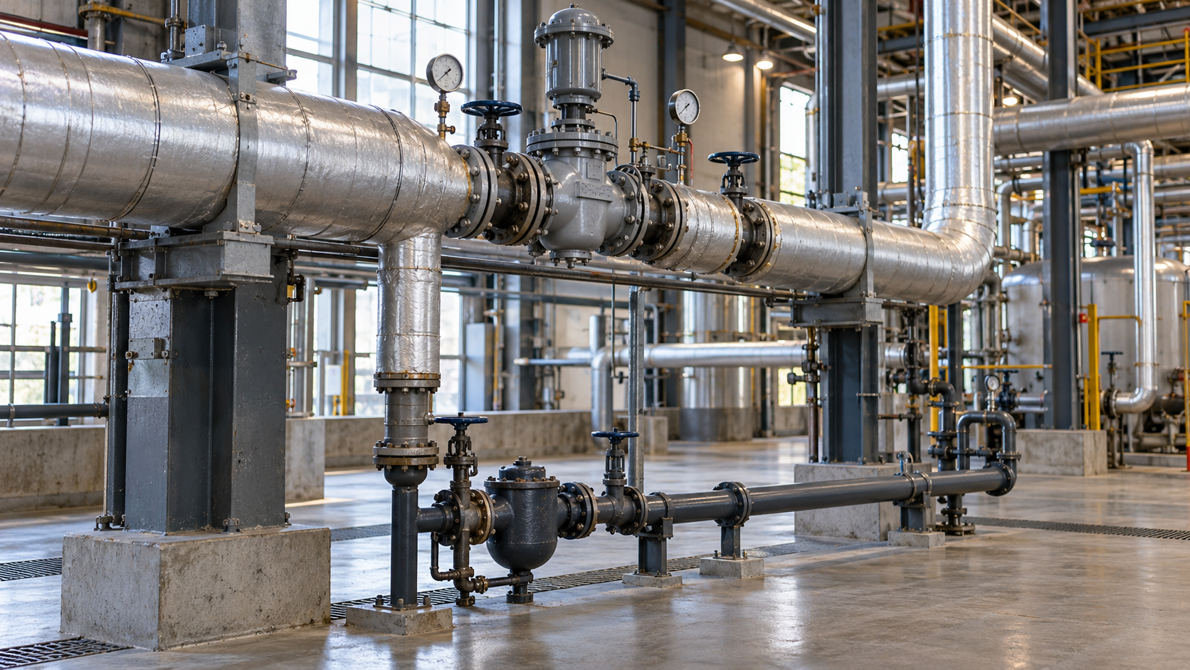
A process steam system must supply each user with the required steam flow at the correct pressure while safely removing condensate. Designing or upgrading such a system therefore involves more than sizing the pipes. The demand profile, pressure-reduction arrangement, condensate drainage and return, and operating conditions must be assessed together.
Where should process steam system design begin?
Start with a demand balance for every steam user, rather than the boiler capacity or the diameter of an existing header. For each item of equipment, establish the steam conditions needed in normal operation, during start-up and at peak load.
| Input data | Why they matter | What to check on site |
|---|---|---|
| Steam flow and operating cycle | Assess simultaneous demand and size piping and valves | Flow in kg/h, operating hours, start-up and process peaks |
| Pressure and temperature | Divide the network into pressure levels and select reduction and protection equipment | User requirements, minimum inlet pressure and source conditions |
| Routing and geometry | Falls, drainage, thermal expansion compensation, supports and access | Lengths, elevations, clashes, fixed points and inspection access |
| Condensate | Select how to discharge and return the hot water | Quantity, pressure, temperature, contamination risk and return destination |
| Existing losses and constraints | Identify which sections actually need upgrading | Insulation condition, leaks, water hammer, pressure drops and fault history |
Simultaneous demand is particularly important. If several machines have high short-term steam requirements but never operate together, simply adding their rated flow rates can lead to oversizing. Conversely, insufficient allowance for start-up may reduce pressure at the points of use. The diversity factor should be derived from the actual production schedule, not assumed automatically.
Steam distribution: pressure, pipe sizing and drainage
Pressure levels and reducing stations
Not every steam user needs the same conditions. A common header can feed areas with different requirements, but appropriately sized pressure-reducing stations are needed for equipment that operates at lower pressure. The regulator must maintain the required downstream conditions as flow changes. Overpressure protection on the low-pressure side must be assessed separately: a pressure-reducing valve does not replace protective safety equipment.
When selecting a reduction station, consider the upstream pressure, required downstream pressure, minimum and maximum flow, steam quality and failure scenarios. The operation of these valves and their response to changing loads are explained in TLV’s technical guide to steam pressure reduction.
Pipe diameters and pressure drop
Pipe size must account for mass flow, steam pressure and condition, permissible velocity and pressure losses along the entire route, including valves and fittings. An undersized pipe can cause excessive pressure drop and make it difficult to supply users. An unnecessarily large pipe increases material costs and heat-transfer area. Design parameters should not be copied directly from another installation, even if its boiler output is similar.
Pipe falls, drain pockets and water-hammer risk
Steam loses heat and partially condenses as it flows through a pipe. Condensate collecting at low points can be entrained by the steam and cause water hammer. The design must therefore provide suitable pipe falls, drainage points, collecting pockets, moisture separation and air venting. Sections upstream of pressure-reducing or control valves and the ends of headers also need attention.
As a manufacturer’s guideline for typical steam mains, rather than a universally applicable legal requirement, TLV recommends, among other measures, a fall of at least 1:100 and drainage points every 30–50 m, with additional points wherever condensate can collect. Actual spacing, falls and geometry must be determined for the specific installation. See TLV’s guidance on steam-main drainage for details.
Simply adding a steam trap will not solve the problem if the pipe has reverse falls, inadequate supports or drainage restricted by high backpressure. Trap locations and maintenance access should be established during design, not after the network has been commissioned.
Condensate return and heat recovery
Condensate is the water formed after steam transfers its heat to the process. Where its quality permits reuse, returning it to the boiler feedwater system can reduce the heating required for fresh water and the need for make-up water and treatment. However, it cannot be assumed that all condensate will return: some processes consume steam directly, and some condensate streams may be contaminated.
How can the energy in returned condensate be estimated?
Suppose a system can return 500 kg of condensate per hour at 80°C, while the make-up water is at 20°C. Using a simplified specific heat capacity of water of 4.18 kJ/(kg·K), the sensible-heat difference is:
500 kg/h × 4.18 kJ/(kg·K) × (80 − 20) K ÷ 3600 = 34.8 kW.
Over 4,000 operating hours, this represents approximately 139 MWh of heat per year. It is an indicative balance of the energy carried by the condensate relative to cooler water, not a measured fuel saving. The actual effect depends on what would have happened to the condensate without the upgrade, pipe and tank losses, deaeration, boiler operation and any flash steam.
Why must condensate return piping be sized separately?
Pressure often drops downstream of a steam trap. Some hot condensate may then flash into steam, creating a mixture of water and flash steam. The return pipe therefore cannot always be sized as though it carried liquid only. Two-phase flow, backpressure, elevation differences and any pumps must be considered. TLV discusses this constraint in its guide to condensate return piping.
Gravity return, pumped return and pressurised systems have different operating requirements. The choice depends on the location of steam users, return-line pressure, condensate quality and boiler-water treatment. Where contamination is a risk, a stream may need to be segregated or its quality monitored. We discuss further ways to use waste energy in our article on industrial heat recovery.
Pipe routes, insulation, controls and maintenance access
A P&ID (piping and instrumentation diagram) should clearly distinguish the steam network, points of use, pressure-reducing stations, drainage points and condensate piping. The physical route must also be agreed: fixed and sliding supports, thermal expansion compensation, wall penetrations, clashes with other services and access to valves and fittings.
Insulation reduces heat loss and the temperature of accessible surfaces. Its type and thickness depend on operating temperatures, safety requirements, surroundings, the cost of losses and the need for removal at maintenance points. Option assessments should cover the entire system: straight runs, flanges, valves and the condition of existing insulation jackets.
| Area | Design decision | Checks after commissioning |
|---|---|---|
| Pressure reduction | Size the station for the load range and protect downstream equipment | Upstream and downstream pressure in different operating conditions |
| Condensate drainage | Drain pockets, steam traps, air vents and maintenance access | Water hammer, temperature and correct condensate discharge |
| Condensate return | Gravity or pumped return, quality control and two-phase flow | Temperature, recovered quantity, backpressure and pump operation |
| Insulation and supports | Reduce losses, accommodate expansion and provide safe access | Damaged insulation, movement and leaks |
In practice, it is worth allowing for measurement of both steam flow and condensate return, as well as pressure and temperature readings at points that make it possible to close the balance. Without these data, it is difficult to distinguish a genuine improvement after an upgrade from changes in output, operating hours or process conditions.
Steam system safety and acceptance inspections
A steam system carries a hot medium under pressure. Even at the concept stage, the permissible operating limits of components, pressure protection, safe shutdown and start-up procedures, material documentation, joint inspection requirements and necessary tests must be established. The final scope depends on equipment classification and how the system is put into service.
EU Pressure Equipment Directive (PED) 2014/68/EU covers pressure equipment and assemblies within its scope with a maximum allowable pressure exceeding 0.5 bar. It sets product requirements; it does not, by itself, establish whether every section of an industrial steam pipeline must be registered with Poland’s Office of Technical Inspection (UDT). The Polish Ministry of Economic Development and Technology describes the PED’s scope and its implementation in Polish law.
The need for technical supervision under Polish law must be checked separately according to the type of piping, medium and operating parameters. Poland’s Office of Technical Inspection (UDT) lists process and steam pipelines among equipment categories, but the classification process and required actions are not the same for every system. Refer to UDT’s guidance on equipment subject to technical supervision and the requirements applicable to the particular equipment category.
Industrial metallic piping projects also use appropriately selected technical standards, including the PN-EN 13480 series. Merely citing a standard does not establish that it is mandatory in every case or determine the requirements for a specific acceptance inspection. The designer and those responsible for conformity assessment should establish the current editions, applicability and documents required for the system.
How should a steam system upgrade be planned?
- Verify the diagram and steam users. Define the network boundaries and identify which machines actually share the same header.
- Collect operating data. Gather flow rates, pressures, temperatures, operating schedules, start-up data and records of failures.
- Check drainage and condensate. Identify low points, the return route, backpressure, the feasibility of returning water to the boiler house and any contamination.
- Compare technical options. Improving drainage and insulation may be sufficient, while other systems require changes to pipe geometry, pressure levels or the entire condensate return arrangement.
- Agree on design, compliance and commissioning. Before installation, confirm the necessary qualifications, documentation, testing scope, production downtime and start-up and acceptance plan.
If an investment is to be assessed for reduced energy consumption, its baseline and proposed energy balances must be compared under consistent production conditions as a separate step. An energy efficiency audit can support that assessment. For projects that have not yet begun, it may also be worth checking whether they qualify for Poland’s white certificate scheme. No steam system upgrade qualifies automatically.
What data should be provided for an initial assessment?
An initial description of the problem is enough to get started: is it a new steam user, pressure drops, poor drainage, no condensate return or an overhaul of the entire route? Useful materials include an existing P&ID or sketch, equipment list, available flow and pressure data, approximate pipe lengths and elevations, information about condensate and photographs of insulation and valves.
From an energy-audit perspective, the first decision is whether the limiting factor lies in distribution, the steam user itself or the steam source. Only then can the scope and expected impact of an upgrade be compared responsibly.
If you are planning a change to a steam system, describe the current arrangement and send Energy Trend the data you have. This will help us define the scope of the necessary energy analysis and any subsequent design or technical work, without requiring every measurement before the first conversation.
Technical and legal sources
- TLV – Best Practices for Condensate Removal on Steam Lines (steam-main routing and drainage practices).
- TLV – Condensate Recovery Piping (two-phase flow and return-pipe sizing).
- TLV – Introduction to Condensate Recovery (heat and water balance).
- Polish Ministry of Economic Development and Technology – PED 2014/68/EU (scope of pressure equipment requirements).
- Poland’s Office of Technical Inspection (UDT) – equipment subject to supervision (equipment categories, including steam and process piping).