Sizing a transformer for an industrial facility starts with establishing how much apparent power the installation actually draws and how this will change after planned investments. Neither the sum of machine ratings nor contracted capacity is sufficient. The final selection must also account for operating conditions, nonlinear loads, continuity-of-supply requirements and energy losses.
How do you size a transformer for a plant’s electrical load?
An MV/LV distribution transformer is sized primarily by its apparent power rating in kVA, whereas production demand is usually expressed as active power in kW. An initial assessment uses the relationship:
S = P / λ, where S is apparent power [kVA], P is active power [kW], and λ is the load’s true power factor.
For nearly sinusoidal waveforms, λ is close to cos φ. If the plant has many variable-frequency drives, rectifiers and other nonlinear loads, cos φ alone should not automatically be inserted into this equation. Current distortion can increase apparent power and thermal losses. In such cases, the power factor and currents should be measured with a suitable power quality analyser.
A transformer’s rated capacity is also different from the connection capacity or contracted capacity. The latter describe other technical and billing constraints. The transformer must accommodate the actual and expected load profile, while its specifications must be coordinated with the available grid connection and the requirements of the relevant distribution system operator (DSO).
Load assessment: nameplate ratings or the actual load profile?
A common mistake is to add together the ratings of every installed device. A motor rated at 90 kW does not continuously draw 90 kW from the grid, and not all machines start at the same time. Conversely, a brief but significant demand peak may be invisible in monthly energy consumption figures.
The best starting point is data from a representative period of plant operation:
- profiles of active power P, reactive power Q and apparent power S at the supply point or switchboard;
- daily, weekly and seasonal variation, including start-ups and shutdowns;
- phase currents, voltages, power factor and phase imbalance;
- harmonics and short-duration events associated with loads that may stress the transformer differently from the average power demand;
- a list of planned machines and their actual contribution to peak demand.
A 15-minute load profile is useful for showing sustained loading and its distribution, but averaging can conceal starting currents lasting only a few seconds. Sensitive installations therefore require historical data to be combined with measurements at a suitable time resolution. We apply a similar distinction between rated power and actual load profiles when discussing electric motors and drives.
The simultaneity factor should not be one arbitrary percentage for an entire factory. Production lines have different operating patterns from a compressor room or seasonal cooling equipment. The load assessment must reflect how these consumers actually operate or are credibly expected to operate.
Example: sizing an MV/LV transformer
Assume that a plant records a peak active power demand of 520 kW. Its true power factor at that peak is 0.92. In two years, a new production line is planned and is expected to increase the coincident peak by 80 kW. For simplicity, we assume the same power factor after expansion and a balanced three-phase load.
| Scenario | Peak active power | Calculated apparent power | Preliminary conclusion |
|---|---|---|---|
| Current operation | 520 kW | 520 / 0.92 = 565 kVA | 630 kVA may be sufficient in terms of continuous load capacity alone |
| After planned expansion | 600 kW | 600 / 0.92 = 652 kVA | 630 kVA would no longer cover the assumed continuous load; 800 kVA is among the ratings to examine further |
In the second scenario, at a line-to-line voltage of 400 V, the approximate load current is I = 652 000 / (√3 × 400) ≈ 941 A. The rated current of an 800 kVA transformer on the 400 V side is approximately 1 155 A. This does not, however, justify approving a purchase. Voltage ratings, temperature rise, starting currents, short-circuit conditions, protection, cooling arrangements and reliability reserve all require confirmation.
The example also shows why a fixed percentage reserve can be misleading. Here, future loading was calculated from a specific expansion plan, rather than automatically adding 20% to every installation.
How much spare capacity should be allowed for growth?
It helps to distinguish three separate needs. The first is confirmed expansion – new machinery, electrification of process heating or more production shifts. The second is uncertainty in the load assessment due to limited measurement quality. The third is backup capacity for critical loads during a fault or when one transformer is taken out of service. Each calls for a different technical solution.
If a plant has a specific expansion schedule, the additional demand should be calculated at the coincident peak. Where plans are only possibilities, it is better to compare phased investment options and the cost of a larger transformer with that of replacing it later. Not all future installed power necessarily contributes to demand at the same time.
Where several investments are interdependent, a broader energy system modernisation assessment can also help: future profiles should reflect changes in technology rather than simply adding together historical peaks.
Thermal conditions and harmonics can change the sizing decision
Temperature, ventilation and installation conditions
The nameplate rating applies under specified operating conditions. High ambient temperature, poor ventilation in the transformer room, installation altitude or enclosure restrictions may require the allowable load to be derated. An 800 kVA transformer cannot be assumed to deliver its full 800 kVA continuously in every room.
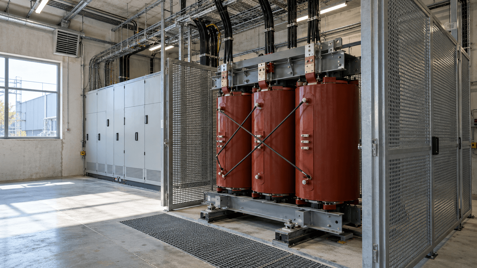
For mineral-oil-immersed transformers, loading under different thermal conditions is covered by IEC 60076-7:2018; for dry-type transformers, the relevant guide is IEC 60076-12:2008. Permissible overloads and cooling conditions must be checked against the documentation for the specific unit. Short-term overload capability is not a permanent reserve for production.
Variable-frequency drives, rectifiers and nonlinear loads
Harmonic currents can increase losses in a transformer’s windings and structural parts. In plants with a high proportion of converter-fed drives, chargers or other nonlinear loads, the kVA figure alone is insufficient. The harmonic spectrum, RMS current, temperatures and permissible operating conditions of the proposed transformer must also be assessed. These relationships are also described in the Schneider Electric technical guide.
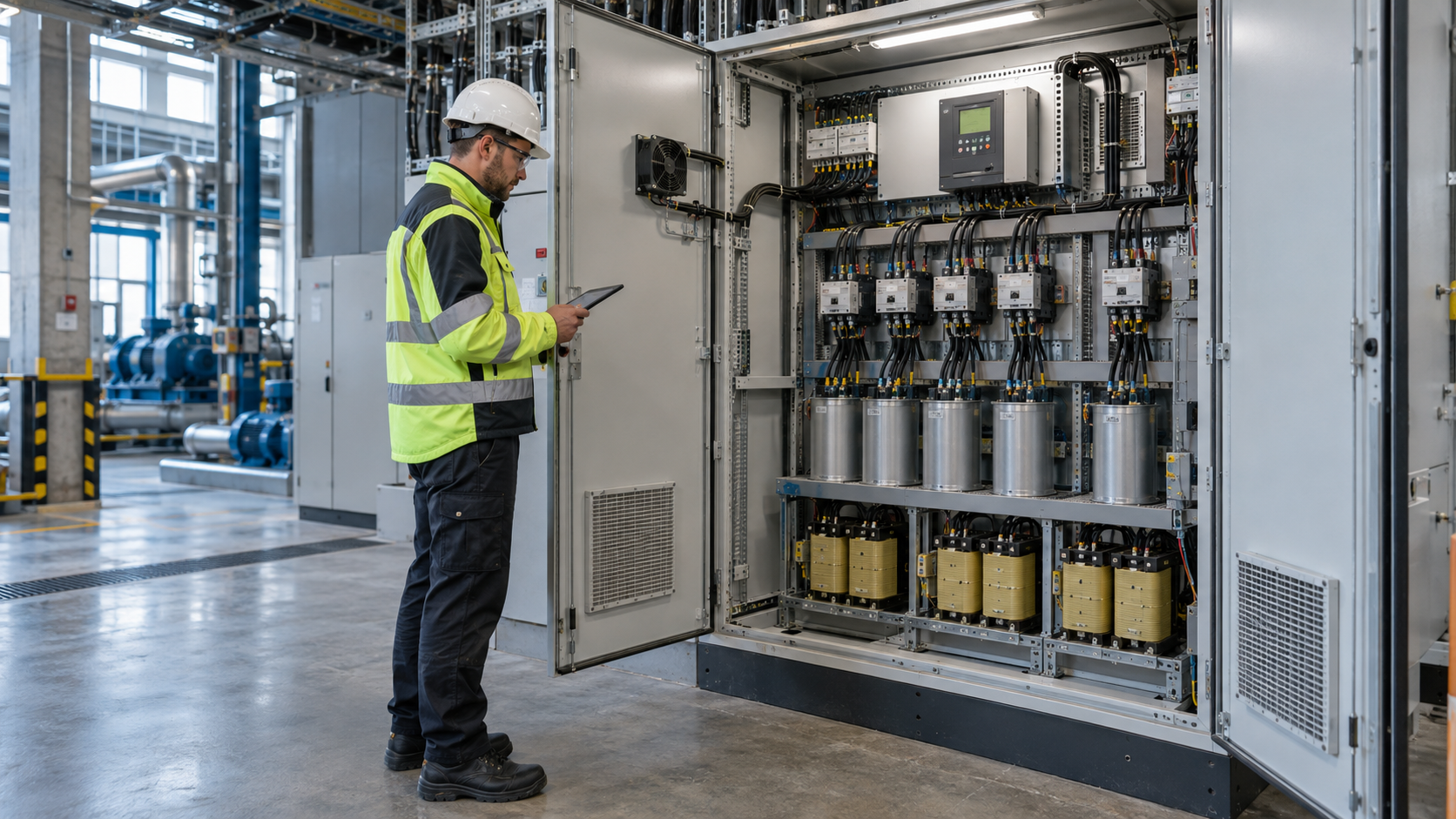
If reactive power compensation is planned, its effect on kVA demand must be considered alongside harmonics and resonance risk. It should not be assumed that installing any capacitor bank will allow a smaller transformer to be selected.
Which transformer specifications matter beyond kVA capacity?
The selected rated capacity is only one parameter. The design must also confirm:
- rated voltages and tap range – compatibility with the MV supply, the required LV voltage and voltage drops within the installation;
- vector group and earthing arrangement – compatibility with the existing network configuration and the requirements for parallel operation, if planned;
- short-circuit impedance uk – its effect on fault currents, voltage drops, and the selection and selectivity of protective devices;
- insulation and cooling type – oil-immersed or dry-type transformer, location conditions, fire protection and environmental requirements;
- no-load losses P0 and load losses Pk – important when comparing operating costs;
- load operating characteristics – starting of large motors, fluctuating loads, phase imbalance and power quality disturbances.
There is no universal short-circuit impedance or vector group that suits every plant. Requirements depend on the supply arrangement and the relevant DSO. For example, ENEA Operator publishes its own technical standards for components of its distribution network in Poland. This does not mean that every provision automatically applies in the same way to a customer’s private installation. The applicable connection conditions, agreements, design and equipment documentation provide the basis for the decision.
One larger transformer or two smaller units?
The number of transformers should follow the production setup and required supply reliability. Two units can allow loads to be divided and maintenance work to be carried out, but do not automatically provide full redundancy. What matters is the switchboard configuration, transfer capability and the load that can actually be supplied after a failure.
| Configuration | Benefit | What needs checking? |
|---|---|---|
| One transformer | Simpler arrangement and usually fewer components to maintain | Single point of failure, scope for planned maintenance outages and future load growth |
| Two transformers sharing the load | Ability to separate some loads and operate more flexibly | Fault currents, switchboard arrangement, permissible switching, losses while both units are energised |
| Two transformers with required N−1 redundancy | Maintaining a defined level of supply after one unit is lost | Whether the remaining transformer, supply path and switchgear can actually carry the critical load or the full required load |
If only part of production needs to continue after a failure, the redundancy design can cover critical loads rather than the full demand of all machines. We discuss how to identify critical loads and assess the consequences of outages in our article on energy supply security for businesses.
Why do lifetime energy losses matter more than purchase price alone?
A transformer may remain energised for much of its service life, including when the plant is not operating. It is therefore worth comparing the total life-cycle cost: purchase, installation, maintenance, no-load losses, load losses, possible downtime and future operating scenarios.
No-load losses P0 occur whenever the unit is energised, even at low loading. Load losses mainly depend on current and increase approximately with the square of the load factor. For a simplified assessment under defined reference conditions, the relationship is Pstrat ≈ P0 + Pk × (S/Sn)². Distorted currents, variable temperatures or a particular duty cycle require a more detailed model.
For example, if P0 were 0.8 kW in the scenario considered and the transformer remained energised for 8 760 hours per year, no-load losses alone would amount to 0.8 × 8 760 = 7 008 kWh/year. This illustrates the relationship; it is neither a specification for a particular unit nor a plant forecast. A complete comparison must also include load losses based on the actual profile, together with the cost and operating arrangements of the system.
When purchasing a new transformer, check compliance with the applicable EU ecodesign requirements. Commission Regulation (EU) No 548/2014, as amended by Regulation (EU) 2019/1783, sets maximum permissible losses for certain transformer categories, among other requirements. Tier 2 requirements have applied since 1 July 2021, subject to exceptions set out in the legislation. Legal limit values are no substitute for comparing actual quotations and load profiles.
What information is needed for a reliable sizing assessment?
| Area | Information required | Why it matters |
|---|---|---|
| Load | Representative profiles of P, Q, S, current and voltage; peak values and their duration | Establishes actual demand and the thermal duty cycle |
| Existing installation | Transformer nameplates and data sheets, single-line diagram, protective devices, settings and measurements | Helps assess compatibility and infrastructure constraints |
| Power quality | Power factor, harmonics, phase imbalance and starting methods for large motors | Affects temperature rise, currents and operating requirements |
| Expansion plan | New loads, commissioning dates, simultaneity assessment and critical loads | Separates foreseeable future demand from hypothetical spare capacity |
| Technical conditions | Connection conditions and DSO requirements, MV/LV, transformer room, ventilation and permissible outages | Confirms whether the option is technically feasible |
| Economics | P0 and Pk of the proposed units, investment costs and operating assumptions | Enables comparison of life-cycle costs |
It is not always necessary to commission extensive new measurements immediately. If reliable readings from a power analyser, monitoring system or operational measurements are already available, start with them. Additional metering should address the questions that the existing data cannot answer.
Common mistakes in transformer sizing
- Sizing from the sum of machine nameplate ratings without considering simultaneity and load profiles.
- Treating contracted capacity in kW as a transformer rating in kVA.
- Applying a fixed percentage reserve unrelated to the expansion schedule.
- Ignoring cooling conditions, enclosures and harmonics when assessing load capability.
- Assuming two transformers provide full N−1 redundancy without checking the circuit arrangement and critical loads.
- Comparing only purchase prices, without considering no-load losses, load losses and operating arrangements.
Where should the investment decision start?
First, I would gather the existing load profiles, transformer documentation and a list of planned machines. I would then examine three scenarios: the current peak, credible demand after expansion and the level of supply needed during a failure. Only then would I compare transformer ratings and the number of units, operating conditions and losses.
If you are considering replacing a transformer or adding another, describe the installation and send us the data you have – even if it is only a load profile, the unit’s nameplate details and the expansion plan. This will help determine which calculations and agreements are needed before making a design decision.
FAQ
Can a transformer be temporarily loaded above its rated capacity?
Some transformers allow specified overloads for a limited period, but this depends on temperature, previous loading, cooling and the manufacturer’s documentation. Such capability should not be used to cover a permanent capacity shortfall without analysis.
Does an improved power factor always mean a smaller transformer can be purchased?
For the same active load, improving the true power factor can reduce current and apparent power. However, it does not automatically address starting currents, harmonics, temperature or redundancy requirements. All these conditions must be checked before selecting a smaller unit.
Technical and legal references
- Schneider Electric – Choice of MV/LV transformer: load assessment, expansion and selection factors.
- IEC 60076-1:2011 – Power transformers, Part 1: general transformer requirements and parameters.
- IEC 60076-7:2018 and IEC 60076-12:2008: loading guidance for mineral-oil-immersed and dry-type transformers.
- Commission Regulation (EU) No 548/2014 – consolidated text and amending Regulation (EU) 2019/1783: ecodesign requirements.
- ENEA Operator – distribution network standards: an example of the scope of a Polish DSO’s technical requirements.