A Blower Door test for building airtightness is not simply a matter of installing a fan in a doorway and reading a single number. For the result to be meaningful, it is first necessary to define exactly what constitutes the test zone, what condition the building should be in, which openings should be closed and which should be temporarily sealed. Only then is a series of pressure differences generated, the corresponding airflow measured, and indicators describing the airtightness of the envelope determined.
The most commonly analysed parameter is n50, i.e. the air leakage rate relative to the volume of the test zone at a pressure difference of 50 Pa. It is a very useful indicator, but it has an important limitation: it shows how airtight the tested building is as a whole, not where the leaks are located. n50 should not be equated with the natural air change rate during normal operation. This is why a good Blower Door test often combines quantitative measurement with leak detection, for example using smoke, an anemometer or a thermal imaging camera.
What does a Blower Door test actually measure?
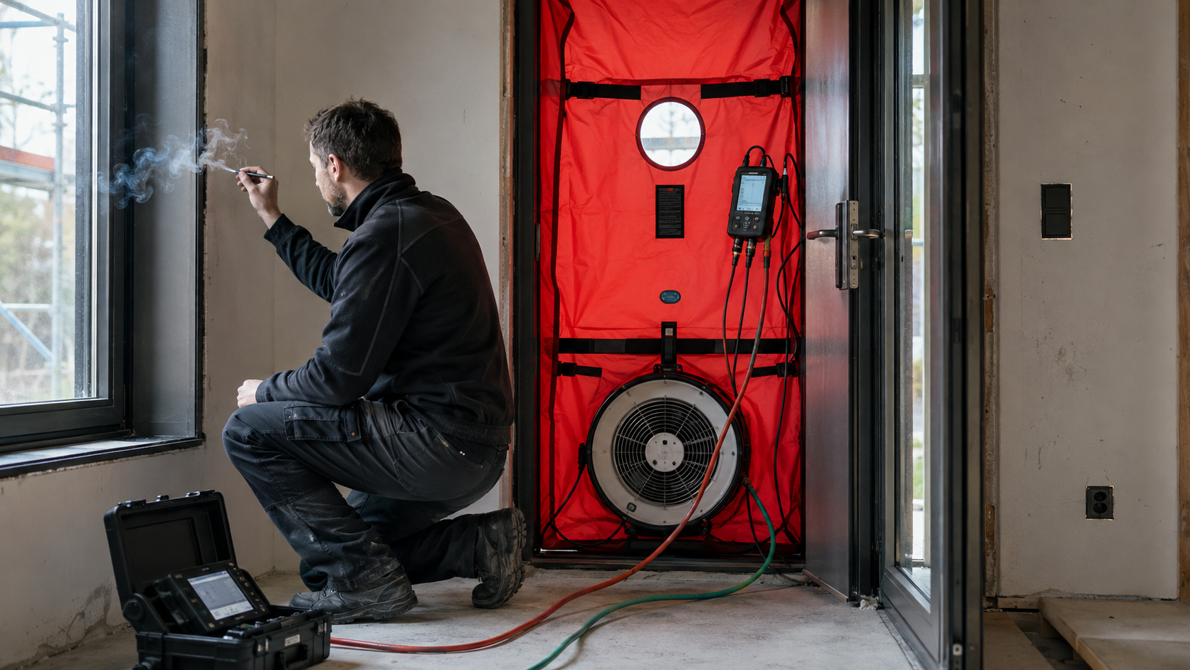
A Blower Door test is a pressurization method used to determine the air permeability of a building or a defined part of it. A calibrated fan is fitted airtight in a doorway or another suitable opening in the envelope. The fan creates negative or positive pressure, while the measurement system records the pressure difference between the inside and outside and the airflow required to maintain it.
The greater the airflow that has to be moved to maintain the same pressure difference, the greater the total leakage of the envelope. The pressure difference achieved on its own is not a measure of airtightness – during the test it is deliberately imposed by the fan. Leakage is assessed primarily from the airflow required to maintain successive pressure levels and from the result determined from the flow–pressure curve.
The measurement does not, however, concern the intended ventilation system as such. How grilles, air inlets, air intakes, exhaust outlets and other intended openings are prepared depends on the purpose of the test and the selected building preparation method.
The current normative basis is the Polish Standard PN-EN ISO 9972:2015-10, which adopts ISO 9972:2015. This Polish Standard replaced the earlier PN-EN 13829:2002. In 2026, ISO confirmed that ISO 9972:2015 remains current.
It is useful to distinguish two things from the outset:
- A Blower Door test measures the total air leakage through the envelope under controlled pressure conditions;
- it does not directly measure natural infiltration during normal operation. Other methods, such as tracer-gas measurements, are used to assess infiltration directly under in-use conditions.
When is it worth carrying out a building airtightness test?
The most useful information comes from a test planned at the right stage. The same equipment can be used for quality control during construction, final acceptance or diagnostics of an existing building, but the purpose of the test should be defined before the building is prepared.
1. During construction – before leaks are covered up
In a new building, a very good time for quality control is when the airtight layer has already been completed but is still accessible for repairs. Windows and doors should be installed and the envelope sufficiently closed to allow a pressure difference to be generated. At the same time, it is not worth waiting until all junctions have been concealed by linings, plasterboard finishes or finishing layers.
PN-EN ISO 9972 indicates that the formal measurement is carried out after the envelope of the tested part of the building has been completed, but it also recognises the value of a preliminary test of the airtight layer during construction, because detected leaks can then be repaired more easily. In practice, such a quality-control test is often more useful for the contractor than simply finding at the end that the completed building does not achieve the required result.
2. After construction – as a final measurement
The final measurement is used to document the airtightness of the completed building in a specified condition. It is particularly important where a specific result has been included in the design, technical specification, contractor agreement, investor requirements or a certification scheme.
In this case, n50 is not the only important element. The report should clearly show the test scope and how all intended openings were prepared so that the result can be reproduced and compared with the requirement.
3. In an existing building – before energy retrofit
In an existing building, a Blower Door test can form part of diagnostics before planned works. It helps determine whether uncontrolled air leakage is a major problem and identify areas that require closer inspection.
An airtightness test should not, however, be treated as a substitute for a full retrofit analysis. It does not determine insulation thickness, select a heat source or define an investment option, and by itself it does not calculate the cost-effectiveness of the entire retrofit. If the objective is broader planning of building improvements, airtightness results are one of the inputs for further analysis and can complement a building energy audit.
4. After sealing works – as a verification test
After repairs have been carried out, it is worth repeating the test with as similar a scope and building preparation method as possible. Only then can the “before” and “after” results be compared reliably. A change in n50 combined with a change in the tested volume, the number of open zones or the way the ventilation system is sealed off can lead to false conclusions.
Preparing a building for a Blower Door test – why is the “test condition” so important?
The most common interpretation error occurs before the fan is even started: two results are compared even though the buildings were prepared differently. ISO 9972 distinguishes three preparation methods depending on the purpose of the test.
Method 1 – building in use
This tests a condition close to normal use as defined by the standard. Natural ventilation openings are closed, while openings of mechanical ventilation or air-conditioning systems serving the whole building are sealed in accordance with the procedure. Windows, doors and hatches in the envelope remain closed.
Method 2 – building envelope test
The objective is to assess the envelope itself as unambiguously as possible. Intended openings are sealed in accordance with the standard, while windows, doors and hatches are simply kept closed. This preparation method is useful, among other cases, when comparing the quality of envelope construction.
Method 3 – test for a specified purpose
The condition of openings is set according to the requirement being verified, for example the design specification, a contractual requirement or another applicable procedure. This is particularly important for acceptance testing, because the result is meaningful only if the preparation method corresponds to the criterion against which it is compared.
Regardless of the selected method, the condition of the building must be documented before the test. In practice, this mainly includes:
- defining the boundary of the test zone and calculating its internal volume;
- closing windows, external doors and hatches in accordance with the selected method;
- positioning internal doors so that the rooms being tested form a single pressure zone, if that is the measurement scope;
- switching off equipment that draws air from or discharges air to the outside, unless it is part of the pressure-generating system;
- appropriately closing or temporarily sealing air inlets, grilles, air intakes, exhaust outlets, ducts and other openings, in line with the purpose of the test;
- filling drainage traps with water or sealing them;
- checking fuel-burning appliances, fireplaces and flues for safety while negative pressure is being generated;
- recording all temporary seals in the test documentation.
In multi-zone buildings, simply “opening all doors” does not always solve the problem. If part of the building is outside the test scope, airflow to adjacent zones may be incorrectly interpreted as leakage to the outside. In larger buildings, the zoning therefore has to be considered carefully and, where necessary, pressures should also be measured in adjacent spaces.
How is a Blower Door test carried out step by step?
Step 1. Define the scope and building parameters
Before the measurement, the tested part of the building, its internal volume V and the envelope area are defined; if the result is to be related to floor area, the relevant net floor area is also determined. These values are not a formality: they are used directly in the calculation of airtightness indicators.
Step 2. Install the fan and measurement system
A calibrated fan is installed airtight in a doorway or another suitable opening. A manometer measures the pressure difference between the inside and outside, while the fan system determines the airflow required to maintain successive measurement points.
Step 3. Measure the zero-flow pressure difference
Before the fan starts generating pressure, the natural pressure difference between indoors and outdoors is recorded. The measurement is repeated after the sequence has been completed. ISO 9972 requires recording for at least 30 seconds and at least 10 values both before and after the test.
If the absolute value of the relevant mean zero-flow pressure differences exceeds 5 Pa, the test does not meet the standard’s validity condition. This is one reason why strong wind or a large stack effect can prevent a reliable test.
Step 4. Generate negative or positive pressure
The fan gradually increases the pressure difference. The test can be carried out under negative pressure, positive pressure or, where required by the purpose and procedure, in both directions.
According to ISO 9972, the measurement series includes:
- at least 5 approximately evenly spaced points;
- successive levels differing by no more than approximately 10 Pa;
- the lowest point at approximately 10 Pa or five times the zero-flow pressure difference – whichever is greater;
- a highest pressure difference of at least 50 Pa; measurements up to 100 Pa are recommended by the standard to improve calculation accuracy where conditions and equipment capacity allow.
For large halls and other non-residential buildings, achieving 50 Pa with a single fan set can be a capacity issue. In such a case, the test should not simply be stopped at a lower pressure and the result presented as a full test meeting all requirements of the standard. In practice, a higher-capacity or additional fan system is used, and in justified cases a large building is divided into smaller zones. If the maximum pressure difference achieved remains between 25 and 50 Pa, the report should clearly state that not all ISO 9972 requirements were met and give the reason; below 25 Pa, the test does not meet the validity criterion of this procedure.
Step 5. Determine the leakage curve
For each point, the pressure difference and the corresponding airflow are known. The relationship is described by a power-law equation:
q = C × (Δp)^n
Regression is used to determine the air leakage coefficient C and the flow exponent n, and then to calculate the leakage airflow at the reference pressure, most commonly q50 at 50 Pa. This means the result is not based on a single fan reading.
Step 6. Calculate airtightness indicators
The most important quantities are:
| Indicator | Meaning | Unit | Use |
|---|---|---|---|
| q50 | air leakage flow rate at 50 Pa | m³/h | baseline result for further calculations |
| n50 | q50 relative to the internal volume V | 1/h | primary indicator used in the Polish Technical Conditions |
| qE50 | q50 relative to the envelope area | m³/(h·m²) | useful when assessing leakage per unit of envelope area |
| qF50 | q50 relative to the net floor area | m³/(h·m²) | used when a requirement or analysis relates the result to floor area |
Not every project needs to use all of these indicators. The criterion should be selected to match the document against which the result is to be compared.
How should n50 be interpreted?
The n50 indicator is calculated using the formula:
n50 = q50 / V
where:
- q50 – air leakage flow rate at a pressure difference of 50 Pa [m³/h],
- V – internal volume of the test zone [m³].
Simple example
Assume that the test zone has a volume of 1000 m³ and the measurement curve gives q50 = 1200 m³/h.
n50 = 1200 / 1000 = 1,2 1/h
This means that at an artificially maintained pressure difference of 50 Pa, the leakage airflow is equivalent to 1,2 times the volume of the tested building per hour. It does not mean that during normal operation the building naturally has 1,2 air changes per hour. The 50 Pa condition is a test condition used to compare airtightness.
The lower the n50 in a correctly performed and comparable test, the more airtight the envelope. The result itself should not, however, be assessed without information about:
- the way the building was prepared;
- the boundary of the test zone;
- the adopted volume V;
- the test direction – positive or negative pressure;
- weather conditions and temperature difference;
- the criterion against which the result is to be compared.
What airtightness values apply in Poland?
An important distinction is needed here between a recommendation in the Polish Technical Conditions and a mandatory criterion arising, for example, from a contract or certification scheme.
In Poland’s currently applicable regulation on the Technical Conditions – whose consolidated text was published in 2022 and for which ELI lists later amending acts – Annex 2, section 2.3.3 gives the following recommended building airtightness values:
| Ventilation type | Recommended n50 value |
|---|---|
| natural or hybrid ventilation | n50 < 3,0 1/h |
| mechanical ventilation or air conditioning | n50 < 1,5 1/h |
Section 2.3.4 also states that, after construction has been completed, it is recommended that residential buildings, collective-residence buildings, public buildings and industrial buildings be subjected to an airtightness test in accordance with the relevant Polish Standard.
This wording matters. These provisions of the Polish Technical Conditions do not establish a universal mandatory n50 acceptance threshold for every building. A criterion may nevertheless become binding if it follows from the design, contract, technical specification, investor requirements, a programme or a certification scheme.
For comparison, under the current Passive House Institute certification criteria, the pressure-test result for a Passive House is n50 ≤ 0,6 1/h. This is a certification-scheme criterion, not a general requirement under Polish law.
What about requirements for windows?
The Polish Technical Conditions separately specify the air permeability of windows and balcony doors at 100 Pa. For low-rise, medium-rise and tall buildings, the limit is no more than 2,25 m³/(m·h) relative to the length of the joint line or 9 m³/(m²·h) relative to area, corresponding to class 3. For high-rise buildings, the respective values are 0,75 m³/(m·h) and 3 m³/(m²·h), i.e. class 4.
These are requirements for components, not for the entire envelope. PN-EN ISO 9972 is used to test a building or part of a building and is explicitly not a method for assessing the air permeability of an individual window or a single joint.
Can weather invalidate the result?
Yes, because wind and stack effect create their own pressure differences across the envelope. The standard notes that obtaining an acceptable zero-flow pressure difference may be difficult when:
- the product of the absolute temperature difference between indoors and outdoors [K] and the height of the tested part [m] exceeds 250 m·K;
- wind speed at ground level exceeds approximately 3 m/s, or the meteorological wind speed exceeds 6 m/s or reaches Beaufort force 3.
These are not stand-alone building “pass/fail thresholds”. They indicate that conditions may make it difficult to meet the measurement-quality criteria. Among other things, the decisive check remains the zero-flow pressure difference before and after the test.
Why doesn’t a good n50 result show where the building leaks?
Because n50 is an aggregate indicator. Two buildings can have the same n50 even though one has a single large leak at the roof-to-wall junction, while the other has dozens of small leaks around service penetrations and windows or doors.
From a repair perspective, that is a major difference. The fan therefore tells us how much air passes through the envelope as a whole. To prepare a list of locations requiring improvement, a controlled pressure difference must be maintained and local diagnostics carried out.
This is also why a single n50 reading should not be used to conclude that “the windows are leaking” or “the roof is the problem”. Such a conclusion requires additional investigation of the specific location.
How are air leaks located during a Blower Door test?
Smoke or a fog generator
Under maintained negative pressure, smoke near a leak is drawn towards the leakage path. The method clearly shows airflow direction and is particularly effective at membrane joints, window and door reveals, service penetrations and hatches.
In buildings with smoke detectors, fire-protection systems or sensitive processes, the use of smoke or fog must be agreed in advance. Not every space is suitable for this type of diagnostics.
Anemometer or thermo-anemometer
A sensitive anemometer can help confirm local air movement at a suspected joint and compare airflow intensity at several locations. It must be remembered, however, that the reading depends on the geometry of the gap, the distance and the orientation of the probe. Local air velocity does not replace a q50 or n50 result determined in accordance with the standard and, without an appropriate method, should not be converted into a “percentage share” of a particular leak in the total leakage.
Thermal imaging camera
Forced airflow can reveal locations on a thermogram where incoming air changes the surface temperature. Thermal imaging is particularly useful when there is a sufficient temperature difference between indoors and outdoors.
Not every thermal anomaly is an air leak. A similar image may be caused by a thermal bridge, differences in material emissivity, solar exposure or moisture. Thermal images are therefore best interpreted together with the test conditions and, where necessary, confirmed using another method.
Tactile and visual checks, and pressure measurements in adjacent zones
In many locations, a simple walk-through under a set negative pressure quickly reveals a perceptible draught. In large or multi-zone buildings, measuring pressure differences between zones provides additional value by helping determine whether air is entering directly from outside or, for example, from an adjacent unheated space.
If the objective is to measure natural infiltration directly rather than envelope airtightness at a specified pressure, other techniques are used, including tracer-gas methods.
Typical air leakage locations in buildings
The Polish Technical Conditions explicitly draw attention to the airtightness of external partitions, joints between partitions, roof-to-wall junctions, service penetrations and window-to-reveal joints. In practical diagnostics, the list of locations to be checked is even broader.
Envelope junctions
- wall-to-roof or wall-to-flat-roof junctions;
- wall-to-ground-floor, wall-to-floor or wall-to-foundation junctions;
- corners, movement joints and interfaces between different structural systems;
- joints between prefabricated elements and sandwich panels.
Service penetrations
- ventilation ducts and flues;
- water, drainage, heating and cooling pipes;
- electrical cables, cable trays and penetrations;
- service penetrations through the roof and external walls.
Windows, doors and their installation
- window- or door-frame junctions with the reveal;
- door and gate thresholds;
- sash seals;
- junctions of window sills, roller shutters and blind boxes with the airtight layer.
Roof, attic and membranes
- membrane overlaps and joints;
- locations where the membrane or airtight layer is penetrated by framing and services;
- areas around chimneys, hatches and roof windows;
- junctions between the membrane and masonry, ring beam or another structural layer.
Elements that are difficult to see after finishing
- electrical boxes and distribution boards in external walls;
- spaces above suspended ceilings;
- service shafts;
- junctions between lightweight curtain walls and the structure;
- unsealed spaces behind built-in elements and linings.
This is why quality control carried out before the airtight layer is covered is so valuable: a leak is then not only easier to find, but also cheaper to repair.
New building, quality control and diagnostics before energy retrofit – these are not the same test
| Situation | Main objective | Most important result | What to watch out for |
|---|---|---|---|
| new building – preliminary test | find workmanship defects while they can still be corrected | leakage map + indicative/comparative result | do not present a preliminary measurement as final acceptance if a different building condition is required |
| new building – final measurement | confirm airtightness against the adopted criterion | documented q50/n50 and other required indicators | building preparation must correspond to the criterion defined by the design, contract or certification scheme |
| existing building – diagnostics | determine the extent and location of uncontrolled air leakage | baseline result + list of locations for further assessment/sealing | do not equate a Blower Door test with a full energy audit or an energy-retrofit design |
| measurement after repairs | verify the effectiveness of sealing works | before/after comparison | keep the same scope, preparation method and calculation method |
From the investor’s perspective, the key question is therefore not “should we do a Blower Door test?” but “what decision should the result enable?”. A building is prepared differently for early quality control, contractual acceptance and diagnostics of an existing hall before retrofit works.
What should a good airtightness test report contain?
Simply stating “n50 = 1,2 1/h” is not sufficient. The report should make it possible to understand how the result was obtained and under what conditions it can be compared with another test.
In practice, it is worth expecting at least:
- identification of the building and the exact scope of the test zone;
- reference to PN-EN ISO 9972 / ISO 9972 and any deviations from the procedure;
- the building preparation method and test direction: positive pressure, negative pressure or both;
- the internal volume V and, where used, the envelope area and net floor area;
- the condition of windows, doors, air inlets, ventilation systems and other intended openings;
- a list of temporary seals installed solely for the purpose of the test;
- information on the measuring instruments and their identification/calibration in accordance with the procedure;
- temperature and wind conditions;
- zero-flow pressure-difference results before and after the sequence;
- pressure–flow points and the resulting leakage curve;
- q50, n50 and any other indicators required for the specific purpose;
- if diagnostics were carried out – a description and documentation of the leakage locations.
Only this set of information makes it possible to distinguish a technically sound result from a number that cannot be verified or compared.
What determines the price of a building airtightness test?
There is no single reliable price that can be given without knowing the building. The cost depends, among other things, on the size and volume of the building, the number of zones, the required fan capacity, the scope of building preparation, the number of measurements, the need to use several fan sets and the scope of leak detection.
A simple final test of a small building is priced differently from diagnostics of a large hall with multiple gates, mechanical ventilation, process installations and several pressure zones. When comparing quotations, it is therefore worth checking not only the price but also exactly what the report includes and whether leak detection is included in the price.
Frequently asked questions about Blower Door tests
Is a Blower Door test mandatory for every new building in Poland?
Not as a universal final acceptance test arising from sections 2.3.3–2.3.4 of the Polish Technical Conditions. In these provisions, the regulations use the wording “recommended airtightness” and state that carrying out a test after construction is “recommended”. A requirement to achieve a specific result may, however, arise from the design, contract, specification, programme or certification scheme.
Does n50 = 1,0 1/h mean one natural air change per hour?
No. It is an air change rate referenced to an artificially generated pressure difference of 50 Pa. Natural infiltration during operation depends on wind, temperature, building height and many other factors.
Does a good n50 mean there are no local air leaks in the building?
No. n50 is an aggregate result. Even with a good result, a single leak can cause discomfort, local cooling or a problem at the junction of envelope layers. Quantitative measurement should therefore be supplemented with leak detection when the objective is quality control or repair.
Can thermal imaging replace a Blower Door test?
No. Thermal imaging shows the distribution of surface temperatures and can help identify locations associated with airflow, particularly when a pressure difference is imposed. It does not, however, determine q50 or n50 values in accordance with the standard, and some thermal anomalies result from thermal bridges or other phenomena rather than air leakage.
Can the test be carried out before all finishing works are complete?
Yes – and it often makes a great deal of sense as quality control if the envelope and airtight layer have already been completed sufficiently to allow the test. Such a preliminary measurement must simply be clearly distinguished from the final measurement if the project requires formal confirmation of the result in a specified building condition.
Normative basis and sources of values
- PN-EN ISO 9972:2015-10 – Polish Standard for determining the air permeability of buildings;
- ISO 9972:2015 – current status of the international standard;
- Polish Technical Conditions – consolidated text and list of subsequent amendments in ELI;
- Passive House Institute – building certification criteria;
- U.S. Department of Energy – materials on Blower Door testing and air-leak detection.
How should the test be approached so that the result is genuinely useful?
First define the purpose of the test, and only then select the building condition and the way openings are prepared. If the purpose is acceptance, the result should correspond to a specific criterion. If the purpose is to find workmanship defects, locating leaks and being able to repair them becomes just as important as n50. In an existing building, the result should be treated as diagnostic data, not as a ready-made energy-retrofit design.
If you want to define the scope of an airtightness test for a specific building, prepare information on its volume and zones, ventilation type, stage of works and measurement objective. This makes it possible to determine the building preparation method and the scope of the report. Contact Energy Trend to discuss the test scope and assumptions.