Insulating industrial pipework reduces energy losses, but its effectiveness depends on much more than the thickness of the insulation. The fluid temperature, ambient conditions, fittings, maintenance access and actual operating hours all matter. An upgrade should start with a survey of missing or deficient insulation and a comparison of technical options and costs over the full service life.
At a plant, a long run of ageing insulation may be easier to notice than a small, permanently hot valve with no cover. Yet pipe length alone does not determine the priority of remedial work. Surface temperature, operating hours and whether the repair can be carried out safely also count.
Where should you look for heat losses in an industrial installation?
Start by inspecting the entire heat distribution route, not only the sections visible from floor level. In steam and hot-water systems, losses occur along straight pipe runs, bends, flanges, valves, strainers, steam traps, vessels and manifolds. Pay particular attention to areas where insulation was removed during maintenance and never reinstated.
In its guidance on insulating steam distribution and condensate return lines, the U.S. Department of Energy highlights uninsulated fittings as well as damaged or wet insulation. These are useful inspection pointers, not ready-made savings figures for a particular plant in Poland.
Survey: what data should you collect?
Record the following in a single table or on an installation diagram:
- section identifier and location, pipe outside diameter and length;
- type of fluid and its temperature under typical and maximum operating conditions;
- approximate annual operating hours, including shutdowns and seasonal operation;
- type, thickness and condition of existing insulation and protective cladding;
- number and types of valves, flanges, strainers, steam traps and other components requiring access;
- ambient conditions: indoors or outdoors, air movement, water, moisture, washdowns and possible mechanical damage;
- operational constraints: access, safe-touch temperatures, hazardous areas, shutdown windows and maintenance-team requirements.
Not every point needs to be measured with high precision straight away. During initial screening, the priority is to distinguish sections with known parameters from those requiring measurement or a review of documentation.
How should you prioritise the work?
| Observation during the survey | What to check first | Possible action |
|---|---|---|
| No insulation on a hot section operating for most of the year | Temperature, length, accessibility, operating hours | Calculate the heat loss and cost of adding insulation |
| Uninsulated valves and flanges | Number of components, temperature, servicing frequency | Consider removable insulation covers |
| Wet or damaged cladding | Source of water ingress, condition of the pipe beneath the insulation | Eliminate the cause and assess whether replacement is needed |
| Long pipe run with sound, dry insulation | Actual thickness, material properties, operating hours | Compare retaining the insulation with adding another layer |
Thermal imaging can help identify discontinuities quickly and compare similar sections. It does not replace a heat-loss balance: the temperature indicated by a thermogram depends, among other things, on cladding emissivity, reflections and ambient conditions. We explain image interpretation in more detail in our article on thermographic inspections of heating installations.
How do you choose an insulation material for pipework?
Selection begins with temperature and operating conditions. Distinguish the fluid temperature from the temperatures reached in service by the insulation layer, facing, adhesive, tape or fasteners. A material may suit a hot pipe even when the finish used with it does not.
Manufacturer documentation should be checked for more than declared thermal conductivity λ. Look at how conductivity varies with mean temperature, the maximum service temperature, moisture behaviour, installation requirements and conditions for using the facing. For example, the ProRox PS 960 pipe insulation documentation describes the insulation properties and the temperature limits of the foil facing separately. This illustrates how to read a product data sheet; it is not a recommendation to use one product in every installation.
Materials and typical limitations
| Solution category | Potential applications | What must be verified |
|---|---|---|
| Mineral wool pipe sections and mats | Hot pipes, bends and larger-diameter components | Temperature range, λ at design temperature, fastening, water protection |
| Rigid PIR/PUR foam pipe sections | Selected installations within the limits of a specific product | Maximum continuous service temperature, reaction to fire, compatibility of cladding and joints |
| Cold-insulation systems, e.g. elastomeric systems or other solutions incorporating water-vapour control | Pipes operating below ambient temperature | Vapour-barrier integrity, condensation risk, temperature range and joint durability |
| Removable covers and insulation blankets | Valves and fittings, flanges, strainers and areas requiring periodic inspection | Ability to refit, sealing after closure, access to equipment |
Do not transfer a hot-water insulation solution to a much higher-temperature steam system without recalculating the design and confirming the product data. With cold fluids, preventing condensation may also be an objective, so reducing heat flow alone is insufficient when selecting the complete system.
Protective cladding and corrosion under insulation
Cladding should protect insulation from water and damage. Outdoors, drainage, the tightness of overlaps, cladding terminations and wind resistance matter. In washdown areas or places subject to intermittent flooding, the sealing of penetrations and joints is also important.
Moisture ingress may increase heat losses and, under certain conditions, contribute to corrosion under insulation (CUI, corrosion under insulation). Replacing the insulation alone without identifying the source of water may therefore quickly recreate the problem. Before covering the pipe again, plan an inspection of its condition and select suitable corrosion protection.
What pipe insulation thickness is justified?
There is no single thickness that can safely be specified for every process pipe. Two pipes of similar diameter may need different solutions because of fluid temperature, operating time, outdoor conditions or the purpose of the insulation.
Calculations comparing the selected options should cover at least:
- pipe diameter, fluid temperature and ambient conditions, including air movement;
- the material λ at the relevant mean temperature, not merely a value quoted at one reference temperature;
- insulation thickness, thermal bridges, supports and breaks in continuity;
- calculated linear heat loss in W/m and the outer surface temperature;
- installation and maintenance costs for each thickness option.
ISO 12241:2022 provides a reference for calculating the thermal properties of installations. The standard sets out calculation rules, but it does not replace an engineering design or automatically prescribe a single thickness for every installation. A complete methodology for calculating pipe heat losses is a separate engineering topic; here the key decision is which options and input data to compare.
Safety requirements for accessible hot surfaces must also be considered. The cladding temperature at which a component can be touched safely depends on the contact conditions and a risk assessment. No arbitrary surface-temperature value should be treated as a universal legal limit for every workplace.
Insulating fittings and steam systems: maintenance access is part of the design
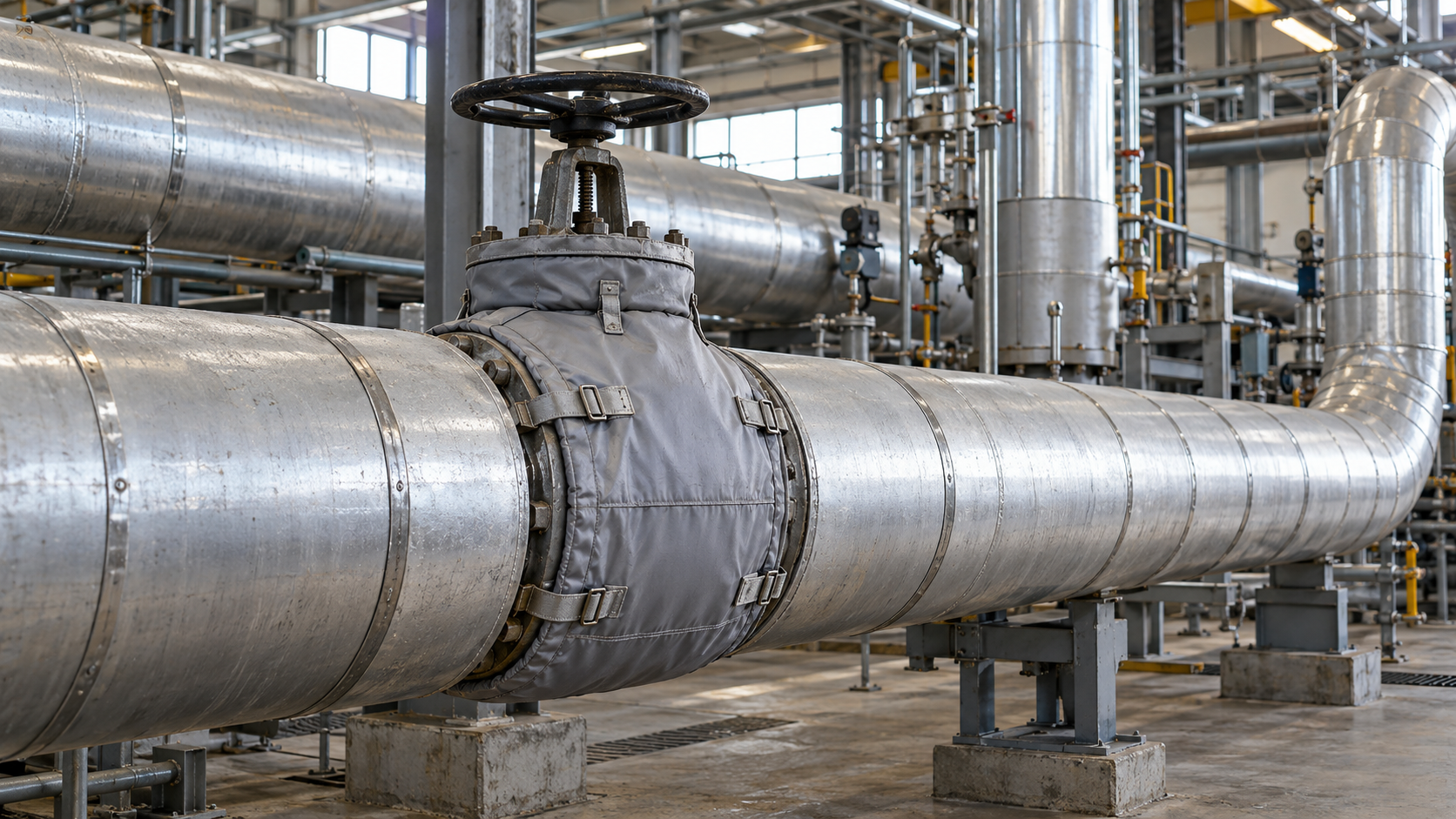
Valves, flanges, strainers, steam traps and manifolds have complex shapes. They are also opened or inspected regularly. If insulation has to be destroyed at each service visit, the risk increases that equipment will remain uninsulated after repair.
For these components, consider purpose-made removable insulation covers. They should be easy to remove and refit while preserving the necessary access to handwheels, nameplates, connections and inspection points. The insulation of steam traps and specialist equipment must comply with the manufacturer documentation. The U.S. DOE likewise recommends removable covers for fittings, subject to operational access requirements.
In steam systems, also assess drainage, condensate lines, vents and possible leak points. Insulation alone will not eliminate losses caused by leaks or faulty steam traps. These are separate diagnostic tasks that need to be included in the work sequence.
How should insulation work be planned and accepted?
Prepare a work schedule by pipe section and component, specifying what will be removed, replaced or added. The maintenance team should define shutdown windows, access to scaffolding or lifts, and safe working procedures for hot and pressurised systems.
Before installation
- Confirm the pipe condition, leak tightness and the cause of any moisture ingress.
- Check the chosen material, thickness, facing, fixings and detailing at supports and penetrations.
- Identify components requiring removable covers and establish how maintenance access will be provided.
- Document the sections and operating conditions before the upgrade to establish a basis for comparison.
At acceptance
- Check that the installed thickness and material type match the design or approved specification.
- Inspect joints, cladding overlaps, terminations, drainage provisions and insulation continuity.
- Verify that fitting covers can be removed and refitted, with unobstructed access for operation and inspection.
- Compare thermal conditions after restart with the values assumed in the documentation and record any deviations.
- Hand over a register of removable components, inspection instructions and as-built documentation to maintenance staff.
New cladding that looks tidy is not proof of effective insulation. Joint quality, thermal bridges, material condition and operating parameters after restart are what matter.
How much can you save? An illustrative economic assessment
A sound calculation starts with the difference between heat loss before the upgrade and heat loss after installing the selected option. Multiply the result in W/m by the pipe length and the actual operating hours under representative conditions. Only then can you calculate the value of the energy saved and compare it with the investment cost.
Suppose the calculated reduction in heat loss for a 30 m section is 80 W/m. The system operates for 5000 hours per year, and the avoidable cost of producing 1 kWh of useful heat is assumed to be 0.30 zł/kWh. The preliminary work cost is 9000 zł. All these values are illustrative assumptions, not data from an Energy Trend project.
| Step | Calculation | Result |
|---|---|---|
| Heat loss avoided | 30 m × 80 W/m | 2400 W, or 2.4 kW |
| Annual energy avoided | 2.4 kW × 5000 h | 12,000 kWh/year |
| Value of energy avoided | 12,000 kWh × 0.30 zł/kWh | 3600 zł/year |
| Simple payback period | 9000 zł ÷ 3600 zł/year | 2.5 years |
This is only a simple calculation illustrating the sequence of steps. It assumes a constant reduction in heat loss and that heat generation can be reduced by the full amount. In an actual facility, check varying loads, heat-source efficiency, any recovery of heat released into the surroundings, shutdown and maintenance costs, insulation service life and possible price increases. If the pipe heats a room that genuinely needs the heat in winter, not all the avoided heat loss will necessarily translate into fuel savings.
Compare the options using life-cycle cost: initial expenditure, maintenance, replacement, access to fittings and the cost of energy lost in subsequent years. For larger projects, an energy efficiency audit can help establish the baseline, assess results and compare the economics of the alternatives.
How can savings be verified after the upgrade?
First define the evidence of performance: calculated linear heat loss before and after, measurements of temperature and ambient conditions, and, where metering is available, changes in fuel or heat consumption adjusted for process load. A thermal-camera image or lower cladding temperature alone cannot establish annual energy savings.
Compare similar operating conditions wherever possible. Otherwise, make appropriate adjustments for temperatures, production and system operating hours. Inspect the insulation again after its first operating cycle and following any maintenance that required covers to be removed.
Reducing distribution losses and industrial heat recovery are two distinct approaches. The first reduces unwanted energy loss from the installation; the second puts waste heat to use where a suitable heat consumer and matching operating schedules exist. Their hypothetical benefits should not be added together without a combined energy balance.
Can an insulation upgrade qualify for Polish white certificates?
Yes, but not automatically. Article 19(1)(1) of Poland’s Energy Efficiency Act lists insulation of industrial installations among the types of measures that improve energy efficiency. Installing pipe insulation does not in itself entitle a project to a certificate: the project conditions, documentation of planned energy savings and the statutory procedure are among the factors that matter.
If an investment is being considered for Polish white certificates, assess eligibility at the planning stage, before taking steps that could affect the requirements for obtaining a certificate. A detailed review of the procedure is a separate process, distinct from selecting insulation.
Common mistakes when upgrading insulation
- Selecting insulation by pipe diameter alone. This ignores temperature, material λ, ambient conditions and the insulation objective.
- Leaving valves and fittings uncovered. Insulation continuity stops at valves and flanges even though they operate for many hours.
- Covering a wet or corroded pipe. New cladding makes later inspection harder while leaving the cause unresolved.
- Failing to provide inspection access. A cover that cannot be readily reinstated may be removed permanently.
- Estimating savings from a single temperature reading. Surface temperature is only part of the information needed for a heat balance.
- Accepting work without baseline conditions. Without information about the pre-upgrade state, it is difficult to verify the actual effect or compare quotations.
How do you prepare data for an initial assessment?
There is no need to commission a full measurement programme immediately. Start with a diagram or photographs of the pipework, approximate diameters and lengths, the type and temperature of the fluid, operating hours, a description of insulation condition, a list of fittings and, if available, heat generation or purchase costs. Mark any difficult-to-access areas and planned shutdowns as well.
These details help identify which sections need more precise calculations, what scope to compare in contractor quotations and where measurement is justified. If you are planning an upgrade, send a description of your system and the data you have via the Energy Trend contact form. An initial discussion helps establish the next steps; it does not replace a design, an audit or an approved contractor quotation.
Practical questions
Does every uninsulated section in a heated production hall mean wasted fuel?
Not necessarily to the same extent. Heat released into the hall may partly meet its heating demand, while outside the heating season it may worsen working conditions or increase cooling loads. The energy balance should reflect how the space is used and how the heat source is controlled.
Can a removable cover remain on a steam trap during operation?
Only if the design and instructions for that particular device allow it and the cover does not obstruct operation or diagnostics. In steam systems, the arrangement must be checked against the manufacturer’s operating requirements.
Technical and legal sources
- ISO 12241:2022 — Thermal insulation for building equipment and industrial installations — Calculation rules. Scope of the methodology for calculating installation heat-transfer properties.
- U.S. Department of Energy — Insulate Steam Distribution and Condensate Return Lines. Inspection of steam, condensate and fitting insulation; technical guidance from 2012.
- ROCKWOOL Technical Insulation — ProRox PS 960. Example of current documentation covering the properties and limitations of a specific product.
- Poland’s Energy Efficiency Act, consolidated text: Journal of Laws 2025, item 711. Article 19(1)(1), eligible type of measure.