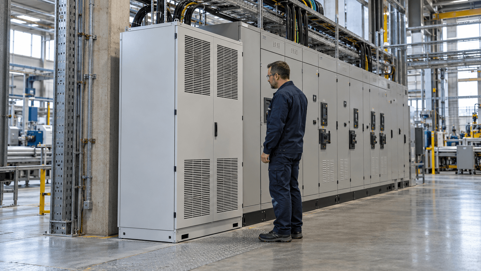
A harmonic filter reduces current distortion in an electrical installation, but not every power quality problem calls for one. Sometimes adjusting a drive’s configuration or fitting a reactor is sufficient; in other cases, an active filter serving an entire distribution board may be needed. The choice depends on measurements, the harmonic spectrum, variations in load and the point in the installation where improvement is required.
When is a harmonic filter necessary?
Harmonics occur when a load draws a non-sinusoidal current. Common industrial sources include rectifiers, electronic power supplies, UPS systems and variable-frequency drives. In a 50 Hz system, for example, the fifth harmonic is at 250 Hz and the seventh at 350 Hz. The mere presence of these components does not mean a filter must be purchased.
An investigation is worthwhile when problems recur: excessive heating of electrical equipment, concerning transformer loading, neutral conductor overload, equipment alarms, capacitor failures or deteriorating power quality. These symptoms do not prove that harmonics are the cause. Overheating may also result from overload, a poor connection, phase imbalance or inadequate cooling.
The first step is to establish what is wrong, where in the installation it occurs and under which operating conditions. Only then can we determine whether filtering is the appropriate remedy. The Danfoss technical paper on harmonic mitigation methods (PDF) also compares the available approaches.
Active filter, passive filter or another solution?
No single technology is best for every installation. The choice depends on the source of distortion, the number of loads, part-load operation and whether the project involves upgrading an existing system or specifying new drives.
| Solution | When to consider it | What to check before choosing |
|---|---|---|
| AC line reactor or DC-link choke in a drive | When a particular rectifier or drive is the source and reducing some harmonics at source is sufficient. | Drive design, permissible voltage drop, load conditions and the performance claimed by the manufacturer. |
| Passive filter | When the harmonic spectrum is relatively stable and a system can be designed for specific harmonic orders or a dedicated drive. | Tuning, network impedance, performance at low load and the risk of resonance. |
| Active harmonic filter (AHF/APF) | When several loads generate varying harmonics and adjustable filtering is needed at a particular distribution board. | Compensation current in amperes, harmonic range, response time, current transformers, measurement location and internal losses. |
| Drive with a multipulse rectifier or active front end (AFE) | When a new drive system can be designed to generate fewer harmonics at its input. | Transformer characteristics, part-load performance, network requirements, total system cost and possible high-frequency interference. |
This comparison is intended to support equipment selection; it is not a ranking of effectiveness. A solution that performs well with one variable-frequency drive may be inadequate for several production lines operating on different cycles. Schneider Electric’s guidance on active harmonic mitigation also highlights network strength, the proportion of drive loads and the need to assess results across the installation.
What does an active harmonic filter do?
An active filter measures current at a specified point and uses a power converter to inject a current that compensates for selected harmonic components. It is typically connected in parallel with the loads. This allows it to respond to changes in the harmonic spectrum and serve a group of machines, provided its position and the current-transformer arrangement allow the relevant currents to be measured.
Do not assume that every active filter can simultaneously eliminate all harmonics, fully compensate reactive power and balance the phases. Available functions, priorities and the combined current limit depend on the model. For example, the Danfoss AAF 007 active filter manual (PDF) sets out its compensation range and priorities and the available device current ratings.
How is a passive filter different?
A passive system uses inductive and capacitive components. It may be tuned to specific frequencies or designed as a dedicated filter for a particular converter. It is generally less flexible than an active system when the installation configuration and load change substantially. Design requires an assessment of resonance and behaviour at low load, when capacitive reactive power may become significant.
It is important to distinguish a passive filter from a detuning reactor in a capacitor bank. The reactor primarily changes the resonance characteristics of the compensation system. It cannot automatically be regarded as an equivalent harmonic filter for the entire installation.
What do the measurements show: THDi, THDu and the harmonic spectrum?
THDi is the ratio of the RMS value of harmonic currents to the fundamental current. THDu describes the corresponding voltage distortion. These are different indicators: an individual load may have high THDi while voltage distortion at the main distribution board remains relatively low. Supply impedance and the distribution of loads are important factors.
Reading a single THD figure from a meter is not enough. You need the spectrum of individual harmonic orders, current values in amperes, time trends and simultaneous voltage measurements. A change in load may reduce THDi expressed as a percentage even when the absolute harmonic current remains unchanged.
Useful references when planning measurements include IEC 61000-4-30:2025 (power quality measurement methods, corrected in 2026) and IEC 61000-4-7 (harmonic and interharmonic measurements). These standards define measurement methods; they do not, by themselves, determine whether to purchase a filter.
Why does high THDi not always mean a large filter is needed?
Consider a simple calculation example: the combined RMS harmonic current is 30 A in two operating states, while the fundamental current changes. This is a simplified model: individual harmonic orders and the potential effects of reactive power compensation are not considered separately.
| Parameter | Operating state A | Operating state B |
|---|---|---|
| Fundamental current I1 | 80 A | 160 A |
| RMS harmonic current Ih | 30 A | 30 A |
| THDi = Ih / I1 × 100% | 37,5% | 18,75% |
In state B, THDi is half as high, but the filter would still have to handle the same assumed 30 A of harmonic current. Sizing equipment solely from the THDi percentage is therefore a mistake. A real installation also requires consideration of the spectrum, maximum values, phase coincidence, load dynamics, neutral current and the required reduction. This example is not a calculation of the rated filter current for a specific device.
What information is needed before selecting a harmonic filter?
An initial assessment can begin with a single-line diagram and a list of major equipment. A technical decision, however, also requires data from the plant’s actual operation. Useful inputs include:
- Single-line diagram: transformers, distribution boards, supply arrangement, point of common coupling and proposed filter location.
- List of nonlinear loads: types of rectifiers and drives, ratings, reactors, built-in filters and planned expansions.
- Currents and spectrum: fundamental component, individual harmonics and their RMS values in amperes, THDi in each phase and THDu.
- Time trends: minimum and maximum values, production-line start-ups, motor starting, changes in production recipes and part-load conditions.
- Network and protection: transformer parameters, short-circuit data, conductor cross-sections, protective devices, thermal conditions and available switchroom space.
- Existing compensation equipment: capacitor bank rating and stages, detuning reactors, controller and history of failures or switching events.
- Investment objective: whether the aim is to protect specific machines, reduce harmonic emissions into the network, improve parameters at a specified plant location or eliminate documented disturbances.
Measurements should be considered at the plant’s supply point, at the distribution board feeding the problematic loads and, where necessary, near the harmonic source. This does not always require three analysers running simultaneously; the scope depends on the problem. Measurements should cover a representative operating cycle, not a random few minutes. There is no universal requirement to measure for seven days for every filter selection: the recording period should reflect process dynamics and the purpose of the analysis.
The assessment point also matters in industrial installations. IEC 61000-2-4:2024 specifies compatibility levels at in-plant points of coupling (IPCs). These levels should not be applied without checking to any busbar, drive terminal or point of connection to the public grid. Acceptance criteria must identify the assessment point and the agreed operating conditions.
Where should the filter be installed, and how does it interact with reactive power compensation?
A filter installed next to a single load limits that load’s influence on the upstream part of the installation. A unit at a common distribution board may compensate harmonics from several machines, but it does not automatically eliminate distortion in every conductor and branch circuit. Installation location therefore forms part of the design, along with the position and polarity of current transformers and the control method.
A separate consideration is reactive power compensation. Capacitors change the network impedance at different frequencies. If a capacitor bank is not suited to the harmonic conditions, certain components may be amplified, capacitors or reactors may become overloaded and protection problems may occur. Before selecting a filter, the configuration of the existing bank must therefore be known and resonance assessed for its possible operating states.
Some AHF models can also compensate reactive current or phase imbalance, but the rated current is then shared between functions according to the particular device’s control logic. Do not promise “simultaneous full filtering and full compensation” in a proposal without checking the limits. A detuned capacitor bank, a passive filter, an active harmonic filter and a static var generator (SVG) perform different primary functions, even if some capabilities overlap.
If particular drives are the main sources, their design and operating modes should also be reviewed. We discuss drive technologies more broadly in our article on electric motors and drives.
How should you compare offers for active or passive filters?
Comparing only the price and a claimed “THDi below 5%” can lead to the wrong decision. Without the measurement point, load and network characteristics, such a claim does not define an unambiguous, verifiable outcome. A request for quotation should specify:
- Scope: which transformer, distribution board, group of loads and assessment point will be covered by the filter.
- Input data: the spectrum, currents and operating scenarios used for sizing, together with any measurement limitations.
- Equipment parameters: continuous compensation current, permissible overload, regulated harmonic orders, response speed, power supply, cooling and enclosure protection rating.
- Integration with the installation: wiring diagram, current transformers, protection, selectivity, capacitor banks and resonance analysis.
- Verifiable target: which values must be achieved, under what operating conditions, using which measurement method and tolerance.
- Life-cycle costs: the unit’s own power consumption, cooling, servicing, spare-part availability, warranty and terms for reconfiguration after process changes.
Two offers with similar rated current may not deliver the same outcome. One filter may handle the dominant harmonics well but leave less capacity for reactive power compensation. Another may require extra space or more extensive cooling. Verifying assumptions before purchase is usually less costly than correcting an unsuitable selection after commissioning.
How should the installation be accepted and operating costs assessed?
Commissioning acceptance should compare conditions before and after installation under as nearly comparable loading conditions as possible and at the same measurement point. The acceptance report should cover at least the current harmonic spectrum, selected phase currents, THDi, THDu, capacitor bank status, filter loading and system behaviour during process changes. If the objective was to meet agreed parameters at the point of connection, measurements must be carried out there.
Operating responsibilities continue after commissioning. An active filter uses energy for its own operation and generates heat that must be removed. Cooling system cleaning, alarm checks, periodic measurements and setting updates after significant load changes should be planned. A passive system requires checks of its inductive and capacitive components and thermal conditions.
Lower THDi does not automatically translate into proportional kWh savings. Any reduction in conductor losses or transformer loading depends on actual currents, resistance and operating time. It must be weighed against the filter’s own consumption and maintenance costs. Reactive energy charges also cannot be assessed reliably from the harmonic spectrum alone. If the concern stems from electricity bills, a separate starting point is an electricity distribution invoice analysis, which does not replace power quality measurements.
Frequently asked questions
Does a THDi of 40% mean a filter is necessary?
No. The THDi percentage alone, without the fundamental current, spectrum, measurement point and technical objective, is not enough to make a purchasing decision. Voltage distortion and the immunity of connected equipment also matter.
Can an active harmonic filter replace a capacitor bank?
Not every model can. Some provide reactive power compensation but have a combined current limit for all their functions. Before replacing a bank, check the required reactive power Q, the device’s operating range and the risk of resonance.
Will a harmonic filter help with voltage dips?
A typical harmonic filter is not designed to correct voltage dips. If the main problem is short-duration reductions in RMS voltage, the source must be investigated separately and another method selected to protect the process.
Where should a plant start?
Start with a brief description of the problem: when it occurs, which equipment is operating at the time and what has already been measured. If available, provide the supply diagram, harmonic spectra or current trends, a list of drives or capacitor bank data. These will help determine the need for further investigation more quickly. A complete set of measurements is not necessary for the first conversation.
If you want to establish whether your installation needs a harmonic filter, another solution at the source of distortion or measurements first, send Energy Trend a description of your installation and the data available. The next steps can then be tailored to the measurement point and technical issue.
Technical references
- IEC 61000-4-30:2025 — power quality measurement methods; edition incorporating the July 2026 corrigendum.
- IEC 61000-4-7:2002+A1:2008 — instruments and methods for harmonic and interharmonic measurements.
- IEC 61000-2-4:2024 — compatibility levels in industrial distribution networks.
- Danfoss: Practical aspects of mains interference reduction (PDF) — a comparison of methods for reducing distortion.
- Schneider Electric: Active harmonic mitigation at low-voltage — selection criteria for industrial installations.